Table of Contents
Advertisement
Quick Links
Advertisement
Table of Contents

Subscribe to Our Youtube Channel
Related Manuals for PCB Piezotronics IMI SENSORS 685B0001A10


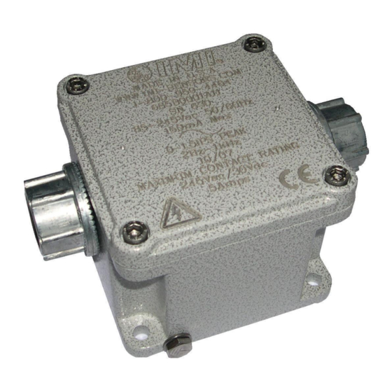
Summary of Contents for PCB Piezotronics IMI SENSORS 685B0001A10
- Page 1 Model 685B0001A10 Electronic Vibration Switch Installation and Operating Manual For assistance with the operation of this product, contact PCB Piezotronics, Inc. Toll-free: 800-959-4464 24-hour SensorLine: 716-684-0001 Fax: 716-684-3823 E-mail: imi@pcb.com Web: www.imi-sensors.com...
- Page 2 Piezotronics, user servicing or repair is critical test. not recommended and, if attempted, may void the factory warranty. Routine PCB Piezotronics maintains an ISO- maintenance, such as the cleaning of 9001 certified metrology laboratory and electrical connectors, housings, and offers calibration services, which are...
- Page 3 50% of the general contact numbers are: replacement cost returned item(s). PCB will provide a price PCB Piezotronics, Inc. quotation replacement 3425 Walden Ave. recommendation for any item whose Depew, NY14043 USA repair costs would exceed 50% of...
- Page 4 PCB工业监视和测量设备 - 中国RoHS2公布表 PCB Industrial Monitoring and Measuring Equipment - China RoHS 2 Disclosure Table 有害物质 汞 镉 六价铬 (Cr(VI)) 多溴联苯 (PBB) 多溴二苯醚 (PBDE) 部件名称 铅 (Pb) (Hg) (Cd) 住房 PCB板 电气连接器 压电晶体 环氧 铁氟龙 电子 厚膜基板 电线 电缆 塑料 焊接...
- Page 5 Component Name Hazardous Substances Lead Mercury Cadmium Chromium VI Polybrominated Polybrominated (Pb) (Hg) (Cd) Compounds Biphenyls Diphenyl (Cr(VI)) (PBB) Ethers (PBDE) Housing PCB Board Electrical Connectors Piezoelectric Crystals Epoxy Teflon Electronics Thick Film Substrate Wires Cables Plastic Solder Copper Alloy/Brass This table is prepared in accordance with the provisions of SJ/T 11364.
- Page 6 685B-Series Electronic Vibration Switch Operating Guide with Enclosed Warranty Information 3425 Walden Avenue, Depew, New York 14043-2495 Phone (716) 684-0003 Fax (716) 684-3823 Toll Free Line 1-800-959-4IMI MANUAL NUMBER: 34181 MANUAL REVISION: ECO# 47640...
-
Page 7: Table Of Contents
Table of Contents Introduction ........................Page 3 General Features Specifications ........................Page 4 Installation and Wiring ..................... Page 5 Installation & Dimensional Drawings Pin Location Diagram- Models with Internal Accelerometer and Triac Relays Pin Location Diagram- Models with Internal Accelerometer and Electromechanical Relays Pin Location Diagram- Models with External Accelerometer and Triac Relays Pin Location Diagram- Models with External Accelerometer and Electromechanical Relays Configuring the 685B ...................... -
Page 8: Introduction
Introduction The 685B-Series is an electronic vibration switch designed to monitor vibration levels and trip an alert when a specified limit is exceeded. A second onboard relay trips an alarm that can be used to shut down a piece of equipment or act as a secondary alert level. -
Page 9: Specifications
Specifications Power Supply Voltage: …… 85-240 VAC, 12-30 VDC (factory set) Power Supply Current: …… 150 mA max Sensor Type: …… Piezoelectric Sensing Element Standard Vibration Ranges: …… 0-5g pk, 0-1.5 ips pk, 0-3 ips pk, 0-50 mils pk-pk, 0-15 mils pk-pk (factory set) ... -
Page 10: Installation And Wiring
Installation and Wiring Installation The 685B-Series is designed to be mounted directly on the equipment to be monitored using a four-bolt pattern. There are also options to retrofit existing 3 bolt pattern installations. (Model 080A209 mounting plate required- see optional accessories on page 13). Use grease between all surfaces to insure specified frequency response, otherwise performance will be degraded. - Page 11 Standard Model Dimension Drawing with ½” NPT Conduit Hubs Inch (mm) PAGE 6...
- Page 12 Explosion Proof Model Dimension Drawing Inch (mm) WARNING AC and DC input signals and power supply voltages could be hazardous. DO NOT connect live wires to screw terminal plugs, and DO NOT insert, remove, or handle screw terminal plugs with live wires connected. PAGE 7...
-
Page 13: Pin Location Diagram- Models With Internal Accelerometer And Triac Relays
Connector and Pinout Diagram The 685B-Series uses screw terminal connectors for all input and output connections. Strip off 0.3” (8mm) of insulation from the connection wire ends. Feed the wire through the access ports, and terminate the wire in the correct location. Once connected, tug lightly on the wire to confirm connection is secure. Pin Location Diagram- Models with Internal Accelerometer and Triac Relays Category Description... -
Page 14: Pin Location Diagram- Models With Internal Accelerometer And Electromechanical Relays
Pin Location Diagram- Models with Internal Accelerometer and Electromechanical Relays Category Description + Power AC Power - Power/Common Earth Ground (Also connect to enclosure safety lug) Normally Closed (when dipswitch is in de-energized position) Alarm Output Common connection Normally Open (when dipswitch is in de-energized position) Normally Closed (when dipswitch is in de-energized position) Alert Output Common connection... -
Page 15: Pin Location Diagram- Models With External Accelerometer And Triac Relays
Pin Location Diagram- Models with External Accelerometer and Triac Relays ® When the external 100mV/g ICP sensor option is specified, an additional terminal block location is added to the 685B-Series. The external accelerometer is connected to +Sensor and –Sensor positions as indicated in the above figure and on the product label locate inside the top cover. -
Page 16: Pin Location Diagram- Models With External Accelerometer And Electromechanical Relays
Pin Location Diagram- Models with External Accelerometer and Electromechanical Relays ® When the external 100mV/g ICP Sensor option is specified, an additional terminal block location is added to the 685B-Series. The external accelerometer is connected to +Sensor and –Sensor positions as indicated in the above figure and on the product label locate inside the top cover. -
Page 17: Configuring The 685B
Configuring the 685B-Series Internal Diagram- Models with Triac Relays The internal diagram displays the location of the control features for the triac versions of the 685B-Series. The alert and alarm set points are adjusted via the single turn potentiometers. The alarm relay is set using the first potentiometer, and the alert relay is set using the third. -
Page 18: Internal Diagram- Models With Electromechanical Relays
Internal Diagram- Models with Electromechanical Relays The internal diagram displays the location of the control features for the relay versions of the 685B-Series. The alert and alarm set points are adjusted via the single turn potentiometers. The alarm relay is set using the first potentiometer, and the alert relay is set using the third. -
Page 19: Using Calibration Mode
Using Calibration Mode The 685B-Series has the unique ability to be calibrated using a 4-20 mA simulator. (IMI Sensors model 699A05, see “Accessories” page) This allows for a much more accurate and quantifiable calibration versus manually attuning the switch. The following steps allow for simple calibration using this configuration. Connect the 4-20 mA simulator signal across the COMM and CAL pins. -
Page 20: Optional Accessories
Optional Accessories Model 080A209 Adapter Plate To retrofit old style vibration switch bolt patterns PAGE 15... - Page 21 Model 699A05 Portable 4-20 mA Calibrator Provides current output for 685B-Series testing, read-out and calibration purposes. Also receives and displays current signal from 4-20 mA proportional output from the 685B-Series. PAGE 16...
-
Page 22: Esd Sensitivity
Warning 2 – ESD sensitivity This equipment is designed with user safety in mind; however, the protection provided by the equipment may be impaired if the equipment is used in a manner not specified by PCB Piezotronics, Inc. Caution 1 – ESD sensitivity Cables can kill your equipment. -
Page 23: Ordering Information/ Model Matrix
Ordering Information/ Model Matrix IMI Part Number: 685B 0 0 0 0 A1 0 Basic Model Series 685B Sensor Option Internal 100 mV/g ICP Sensor ® External 100mV/g ICP Sensor External 100 mV/g ICP Sensor (Low Frequency) Internal 100 mV/g ICP Sensor (Low Frequency) ®...
Need help?
Do you have a question about the IMI SENSORS 685B0001A10 and is the answer not in the manual?
Questions and answers