
Related Manuals for MiTAC MX1-10FEP Series


Summary of Contents for MiTAC MX1-10FEP Series
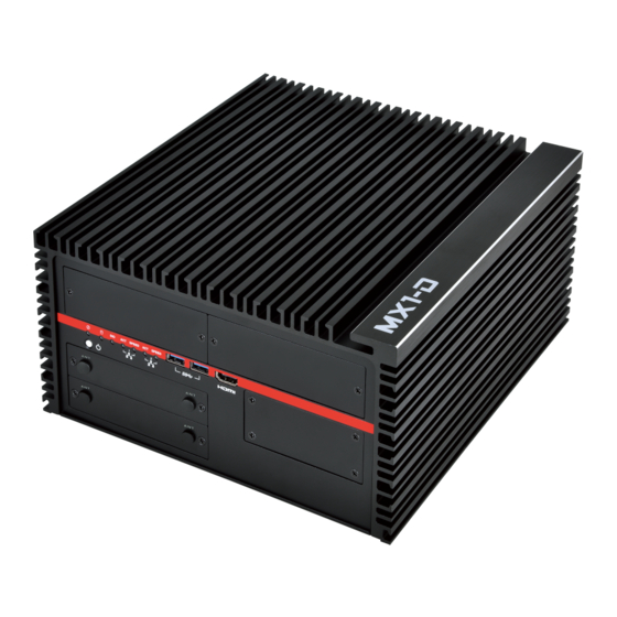
- Page 1 MX1-10FEP Series User Manual V1.6 aster Series Embedded System Intel® Coffee Lake Xeon-E / Core-i Processors Powerful, Versatile, and Rugged & Reliable...
- Page 2 MX1-10FEP-D Quick Assembly Guide 5615D8050002 Open Bottom Cover Install/Remove Removable 2.5” HDD Assembly of PCIe Bracket and Holder 3-1. Loosen M3 screws(x 4) from PCIe bracket. 2-1. Loosen M3 screws(x 4) from HDD cover. 3-2. Install PCIe card and fix with M3 screws( x 2). 1.
-
Page 3: Preface
MX1-10FEP-D GFX / AI Card Options Model Name Display Connectors Memory NVIDIA Quadro P400 3 x mDP1.4 2GB GDDR5 NVIDIA Quadro P620 4 x mDP1.4 2GB GDDR5 NVIDIA Quadro P1000 4 x mDP1.4 4GB GDDR5 NVIDIA Quadro P2200 4 x DP1.4 5GB GDDR5 NVIDIA Tesla T4 16GB GDDR6... - Page 4 MiTAC Corp., Ltd. All information and specification provided in this manual are for reference only and remain subject to change without prior notice.
- Page 5 Safety Information WARNING! / AVERTISSEMENT! Always completely disconnect the power cord from your chassis whenever you work with the hardware. Do not make connections while the power is on. Sensitive electronic components can be damaged by sudden power surges. Only experienced electronics personnel should open the PC chassis.
- Page 6 Ordering Information Model Number Description MX1-10FEP-C246 Fanless Embedded System with Intel® C246 Chipset. 2x260Pin DDR4 SO-DIMM 2666Mhz up to 32GB, 1xHDMI, 1xDisplayPort, 1xDVI-I, 2xGbE LANs, 6xUSB3.0, 2xUSB2.0, 2xCOM, 9~48V DC-in, L6 System w/o AC Adaptor. MX1-10FEP-C246-AC300 Fanless Embedded System with Intel® C246 Chipset. 2x260Pin DDR4 SO-DIMM 2666Mhz up to 32GB, 1xHDMI, 1xDisplayPort, 1xDVI-I, 2xGbE LANs, 6xUSB3.0, 2xUSB2.0, 2xCOM, 9~48V DC-in, L6 System with 300W AC Adaptor, EU + US power cords.
- Page 7 Packing List Q’ty Item Description MX1-10FEP or MX1-10FEP-D Embedded System CPU Cooler (passive) Quick Installation Guide (1 page) Wall Mount Brackets (2 pcs in 1 set) Driver CD Screw Pack (For HDD, SATA cable, and Wall Mount Bracket) 3-pin Terminal Block Power Connector (For DC Power Input) 4-pin Terminal Block Power Connector (For PWM fan) 2-pin Terminal Block Power Connector (For Remote Power Control) DVI to VGA converter...
- Page 8 Optional Xpansion Modules and Accessories Model Number Description MS-48CDN-DT10 Expansion Module with 4 x RS232 / 422 / 485, 8-bit Isolated DIDO (4 x DI, 4 x DO) MS-04LAN-R10 Expansion Module with 4 x Intel i210-IT Giga LAN, RJ45 Port MS-04LAN-M10 Expansion Module with 4 x Intel i210-IT Giga LAN, M12 Port MS-04POE-R10...
- Page 9 MX1D-02INFAN-GFX Internal 4020 FAN Kit for GFX Card (for MX1-10FEP-D Model) MX1D-02INFAN-TP4 Internal 4028 FAN with FAN duct Kit for T4/P4 Card (for MX1-10FEP-D Model) MX1-01EXFAN External FAN Kit (for both MX1-10FEP and MX1-10FEP-D Models) MP-116RCN-P10 MP-116RCN-P10_(PCIEX1 + PCIEX16) Riser Card w/ Single Packing (for MX1-10FEP-D Model) *This is option.
-
Page 10: Table Of Contents
CONTENTS PREFACE ............................... 1 CHAPTER 1: INTRODUCTION ......................10 1.1 Overview ..........................10 1.2 Product Features ........................10 1.3 MX1-10FEP & MX1-10FEP-D CPU Options ................11 1.4 Hardware Specification ......................12 1.5 Mechanical Specification ..................... 16 1.6 System I/O Placement ......................18 CHAPTER 2: DIP SWITCH SETTING AND PIN DEFINITION .............. - Page 11 INTRODUCTION This chapter provides the MX1-10FEP Embedded System product overview, including features, hardware and mechanical specifications.
-
Page 12: Chapter 1: Introduction
I/O placement. 1.1 Overview MiTAC’s MX1-10FEP embedded system is the next generation embedded system with Intel® Coffee Lake C246 workstation chipset which can support Xeon and Core-i LGA1151 socket type processor. The excellent performance, powerful processor, OCP/OVP power protection, and expandable design provide the solution for every complicated task and most types of application. -
Page 13: Mx1-10Fep & Mx1-10Fep-D Cpu Options
1.3 MX1-10FEP & MX1-10FEP-D CPU Options Processor Name Cores Threads TDP Intel® Xeon® E Processor Intel® Xeon® E-2226GE Processor, 12M Cache, up to 4.60 GHz Intel® Xeon® E-2176G Processor, 12M Cache, up to 4.70 GHz Intel® Xeon® E-2124G Processor, 8M Cache, up to 4.50 GHz Intel®... -
Page 14: Hardware Specification
1.4 Hardware Specification SYSTEM 8th Gen Intel® Coffee Lake Xeon-E / Core-i LGA1151 Socket Processor TDP Max. 80W ® Chipset Intel C246 System Memory DDR4 2666MHz, 2 x 260-pin SO-DIMM, Max. 32GB (Xeon: ECC; Core-i: Non-ECC) ® Graphics Intel HD Graphics Display Interface HDMI, DisplayPort, DVI-I Storage Slot... - Page 15 POWER REQUIREMENT Power Input 9~48V Wide Rage DC Input w/ Terminal Block Connectivity MECHANICAL Thermal Design a. MX1-10FEP: Fanless b. MX1-10FEP-D: Fanless or with 2 x 40m x 20cm Internal System Fan (External System Fan Kit as Option in Accessories) Mounting Wall mount a.
- Page 16 ® OS Support Windows 10 64-bit, Linux (support by request) *Notes : Installation in Restricted Access Location (RAL) A restricted access location is a designated area within an incident area (High or Low temperature environment) With authorized people can enter for a period of time and for a specific purpose.
- Page 17 *Note : The following configurations in ultimate use might cause system shut down unexpectedly. - 12 x LANs or 10 x PoE LANs with some NVMe SSD models (Please check the available list with our sales contact window) - 12 x LANs or 10 x PoE LANs with mPCIe or M.2 Wifi Card (Not include CNVi Wifi Card. Please check the available list with our sales contact window) *Note : Please read the BIOS release note before re-flashing BIOS.
-
Page 18: Mechanical Specification
1.5 Mechanical Specification MX1-10FEP Mechanical Dimension: 268 mm x 246 mm x 108 mm PCI Express x16 Slot Maximum Card Dimension: 111.15 x 200 x 18.7mm with mPCIe PoE Module 111.15 x 230 x 18.7mm w/o mPCIe PoE Module... - Page 19 MX1-10FEP-D Mechanical Dimension: 268 mm x 246 mm x 128 mm PCI Express x16 Slot Maximum Card Dimension: 145 x 221 x 43mm w/o mPCIe PoE Module PCI Express X16 + X1 Dual Slot (Default) PCI Express X8 + X8 Dual Slot (Optional) ...
-
Page 20: System I/O Placement
1.6 System I/O Placement Front I/O: Rear I/O (MX1-10FEP):... - Page 21 Rear I/O (MX1-10FE-D): *Notes: The recommended dimension of USB cable connector or device for USB2.0 ports is 9mm height x 19mm width when all the other I/O ports are occupied. It still needs to depend on the DisplayPort connector and other devices’ dimension to aviod the interference.
- Page 22 Xpansion Module (Optional) Configuration Table *Notes : ME-02POE-R10 Xansion module is installed in mPCIe slot, so the maximum configuration is 2 x ME-02POE-R10 at the same time due to the quantity of mPCIe slot. For example, the module could be installed in door#1+door#2, door#2+door#3, or door#1+door#3, but cannot be installed in door#1+door#2+door#3.
- Page 23 DIP SWITCH SETTING AND PIN DEFINITION This chapter provides information about how to set up the dip switch and use internal I/Os of MX1-10FEP Embedded System hardware.
-
Page 24: Chapter 2: Dip Switch Setting And Pin Definition
CHAPTER 2: DIP SWITCH SETTING AND PIN DEFINITION This chapter provides information about how to set up the dip switch, and use internal I/Os of MX1-10FEP Embedded System hardware. 2.1 Jumper and Internal Connector Overall Placement Board to Board connector DIMM sockets Board to Board connector Mini PCIe slot 2... -
Page 25: Dip Switch Setting
Mini PCIe Slot 1 PCIE X1 SATA Signal Header SATA Power Header 2.2 DIP Switch Setting Location #G Signal ATX mode Down AT mode Location #F Switch setting Mode 1-2 COM 1 Switch setting Mode 3-4 COM 2... -
Page 26: Internal Connector Pin Definition
2.3 Internal Connector Pin Definition Location #Q – 1 SATA Connector Signal Name VCC3 VCC3 VCC3 +12V +12V +12V SATAHDR_TXP0_C SATAHDR_TXN0_C SATAHDR_RXN0_C SATAHDR_RXP0_C... - Page 27 Location #O/#Y – 2 and 3 SATA Power Header Signal Name VCC3 +12V +12V Location #N/#X – 2 and 3 SATA Signal Header Signal Name Description Ground SATAHDR_TXP_C SATA DATA Transmit(positive) SATAHDR_TXN_C SATA DATA Transmit(negative) Ground SATAHDR_RXN_C SATA DATA Receive(negative) SATAHDR_RXP_C SATA DATA Receive(positive) Ground...
- Page 28 Location #P – Fan Header Signal Ground +12V CPU_FAN_TACH CPU_FAN_CTRL Location #H – M.2 Key E Slot...
- Page 29 Location #S – M.2 Key M Slot...
-
Page 30: External Connector Pin Definition
Location #L/#M – 12V Power Header for PoE Xpansion Signal Ground +12V +12V Location #J/#K – 5V Power Header for Reservation Signal Ground 2.4 External Connector Pin Definition 3-pin terminal block for DC Input Signal +9~48VIN DC IN Ignition (IGN) - Page 31 4-pin Terminal Block for PWM Fan Signal Ground +12V System_FAN_TACH SYSTEM_FAN_CTRL 2-pin Terminal Block for Remote Power ON/OFF and Reset Signal Ground EXT Reset Ground EXT_PWRBT_ON/OFF...
- Page 32 COM#1 / COM#2...
-
Page 33: Xpansion Module Ms-48Cdn-Dt10 (Optional)
2.5 Xpansion Module MS-48CDN-DT10 (Optional) This Module MS-48CDN-DT10 consists of two parts, one is Serial COM, and the other is Digital IO function. Please see the guideline about how to set up this Module correctly. COM Port Setting a. Location MS-48CDN-DT10 has total 4 x COM port. - Page 34 (2) Powered COM enable switch (3) Powered COM power source selection switch (4) COM Mode setting switch...
-
Page 35: Xpansion Module Ms-04Lan-M10 (Optional)
Digital IO Port MS-48CDN-DT10 has total 8-bit GPIO, the position is as follows. 2.6 Xpansion Module MS-04LAN-M10 (Optional) This Module is a Giga LAN module, which supports four M12 type interfaces. Combined with MS-01PON-S10 to support PoE (typeA). M12 Code A LAN Module Pin definitions... -
Page 36: Xpansion Module Ms-01Ign-S10 (Optional)
2.7 Xpansion Module MS-01IGN-S10 (Optional) This Module MS-01IGN-S10 can detect vehicle ignition status and control the on/off delay time setting. This document is used to guide how to set up this power ignition module correctly. a. Location b. Function Emergency reset button This button is for engineering use only. - Page 37 SYSTEM SETUP This chapter provides information about how to set up the MX1-10FEP Embedded System hardware installation.
-
Page 38: Chapter 3: System Setup
CHAPTER 3: SYSTEM SETUP This chapter provides information about how to set up the MX1-10FEP Embedded System hardware installation. Warning: The edge of MX1-10FEP aluminum extrusion fins is a little bit sharp. Please be careful when you move the unit, do the installation, and operate the embedded system! 3.1 1 2.5”... - Page 39 Fasten the screws to assemble the HDD/SSD to the bracket Insert the HDD/SSD tray back to main chassis and fasten the screws on the door *Notes: Please keep the unit in horizontally. It will make it easierly to insert the HDD tray back to machine.
-
Page 40: Nd And 3 Rd 2.5" Sata Hdd/Ssd Installation
3.2 2 and 3 2.5” SATA HDD/SSD Installation Remove the GND screws from the rear bezel Remove the bottom cover Loosen four HDD bracket screws and pull the bracket out of the unit... - Page 41 Fasten 2 and 3 HDD/SSD to the bracket as following concept drawing Fasten four bracket screws to the main unit Follow the drawing to do the SATA cable routing...
-
Page 42: Cpu/Cpu Heatsink/Dram Installation
3.3 CPU/CPU Heatsink/DRAM Installation Remove the GND screws from the rear bezel Remove the bottom cover... - Page 43 Loosen four M4 screws from the main chassis Before this step, please check that you already loosen two GND screws. And then pull the main chassis from the aluminum extrusion. There are chipset thermal pads (L6), and two guide pin on the aluminum extrusion, so you need to force to pull it out.
-
Page 45: Rtc Battery Maintenance
3.4 RTC Battery Maintenance Preparation for disassembly: Flathead Screwdriver (The battery holder is designed for great vibration resistant and harsh environment use, so it needs to use a tool to disassemble the coin battery) Insert flathead screwdriver to the gap of one side of RTC battery vertically. Rotate the screwdriver at around 45 degrees to loosen the coin battery... -
Page 46: External Fan (Optional) Installation Guide
3.5 External Fan (Optional) Installation Guide Twist the thumbscrews counterclockwise on external fan Align the edge of external fan bracket as green arrows, and align the metal latch as red arrow direction. Then insert the fan to the center of housing Tighten thumbscrews to fix the external fan, and connect the 4-pin cable to the PWM fan connector from rear I/O *Notes: Please don’t do any operation when the system is booted up. - Page 47 BIOS SETUP This chapter provides information about how to set up BIOS and use BIOS menu items to adjust basic function settings.
-
Page 48: Chapter 4: Bios Setup
CHAPTER 4: BIOS SETUP This chapter provides information about how to set up BIOS and use BIOS menu items to adjust basic function settings. 4.1 Main Page Field Name BIOS Vender Default Value AMI Megatrends Comment This field is not selectable. There is no help text associated with it. Field Name BIOS Version Default Value... - Page 49 Field Name Total Memory Value Display the installed memory size. Comment This field is not selectable. There is no help text associated with it. Field Name Memory Frequency Value Display the installed memory frequency. Comment This field is not selectable. There is no help text associated with it. Field Name SATA#1 / SATA#2 / SATA#3 / M.2#4 / mSATA#5 / mSATA#6 Value...
-
Page 50: Advance Page
4.2 Advance Page Advanced Description ► Onboard Devices Onboard Device Configuration ► CPU Configuration CPU Configuration Parameters ► Trusted Computing Trusted Computing Settings ► WatchDog WatchDog Configuration ► Super IO Configuration System Super IO Chip Parameters. ► NCT6116D HW Monitor Monitor hardware status ►... - Page 51 4.2.1 Onboard Device ► Onboard Devices Value Onboard Device Configuration Enable/Disable processor Turbo Mode (requires Intel Disabled / [Enabled] Speed Step or Intel Speed Shift to be available and Turbo Mode enabled). Specify what state to go to when power is re-applied after S0 State / [S5 State] State After G3 a power failure (G3 state).
- Page 52 HD Audio Control Detection of the HD-Audio device. Disabled / [Enabled] Disable = HAD will be unconditionally disabled Enabled = HAD will be unconditionally enabled. 4.2.2 CPU Configuration ► CPU Configuration Value CPU Configuration Parameters CPU Configuration Type Intel® xxxx® xxxxxx xxxxxxx 0xXXXX Speed XXXX MHz...
- Page 53 Intel Trusted Execution Enables utilization of additional Technology hardware capabilities provided by [Enabled] / Disabled Intel® Trusted Execution Technology. Changes require a full power cycle to take effect. 4.2.3 Trusted Computing ► Trusted Computing Value Trusted Computing Settings TPM20 Device Found Firmware Version: Vendor: xxxxxx...
- Page 54 reboot during restart in order to change State of Security Device. 4.2.4 WatchDog ► WatchDog Value WatchDog Configuration WatchDog [Disabled] / Enabled Enables or Ddisables WatchDog function. 4.2.5 Super IO Configuration...
- Page 55 ► Super IO Configuration Value System Super IO Chip Parameters. Super IO Configuration Super IO Chip NCT6116D ► Serial Port 1 Configuration Value Set Parameters of Serial Port 1 (COMA)
- Page 56 Serial Port 1 Configuration Serial Port Disabled / [Enabled] Enable or Disable Serial Port (COM) Device Settings IO=3F8h; IRQ=4 Change settings [Auto] / IO=3F8h; IRQ=4 Select an optimal settings for Super / IO=3F8h; IRQ=3, 4, 5, 6, 7, 9, 10, IO Device 11, 12 / IO=2F8h;...
- Page 57 ► NCT6116D HW Monitor Value Monitor hardware status PC Health Status Hardware Monitor Alert Enable [Disabled] / Enabled If Enabled, POST monitors voltage, temperature, and fan status. If these values are out of range, BIOS display warning message and turn on beep sound.
- Page 58 VSB3V xx V 4.2.7 S5 RTC Wake Setting ► S5 RTC Wake Setting Value Enable System to wake from S5 using RTC alarm Wake System with Fixed [Disabled] / Fixed Time / Enable or disable System wake on Time from S5 Dynamic Time alarm event.
- Page 59 ► Network Stack Value Network Stack Settings Configuration Network Stack [Disabled] / Enabled Enable/Disable UEFI Network Stack 4.2.9 NVMe Configuration...
-
Page 61: Security Page
4.3 Security Page Security Value Description Password Description Administrator Password xxxx Set Administrator Password User Password xxxx Set User Password ► HDD Security drive(EX: HDD Security Configuration xxxxxxxxxxxxx) for selected drive ► Secure Boot Secure Boot configuration ► BIOS Update BIOS Update support 4.3.1 Secure Boot... - Page 63 ► Secure Boot Value Secure Boot configuration System Mode xxxx Secure Boot [Disabled] / Enabled Secure Boot feature is Active if Secure Boot is Enable, Platform Key(PK) is enrolled and the System is in User mode. The mode change requires platform reset Secure Boot Mode Standard / Secure Boot mode options: Standard or Custom.
- Page 64 Factory Key Provision [Disabled] / Enabled Install factory default Secure Boot keys after the platform reset and while the System is in Setup mode ► Restore Factory Keys [Yes] / No Force System to User Mode. Install factory default Secure Boot key database ►...
- Page 65 3. EFI PE/COFF Image(SHA256) Key Source: Factory, External,Mixed ► Authorized Signatures [Details] / Export / Enroll Factory Defaults or load certificates from Update / Append / a file: Delete 1.Public Key Certificate: a)EFI_SIGNATURE_LIST b)EFI_CERT_X509 (DER) c)EFI_CERT_RSA2048 (bin) d)EFI_CERT_SHAXXX 2.Authenticated UEFI Variable 3.
- Page 66 b)EFI_CERT_X509 (DER) c)EFI_CERT_RSA2048 (bin) d)EFI_CERT_SHAXXX 2.Authenticated UEFI Variable 3. EFI PE/COFF Image(SHA256) Key Source: Factory, External,Mixed 4.3.2 BIOS Update...
-
Page 67: Boot Page
4.4 Boot Page Boot Value Description Setup Prompt Timeout Number of seconds to wait for setup activation key. 65535(0xFFFF) means indefinite waiting. Bootup NumLock State On / [Off] Select the keyboard NumLock state FIXED BOOT ORDER Priorities Boot Optoin #1 [USB Floppy] / CD/DVD / USB Sets the system boot orfer CD/DVD / Hard Disk / USB Key /... - Page 68 USB Hard Disk / Network / Disable Boot Optoin #3 USB Floppy / CD/DVD / [USB Sets the system boot orfer CD/DVD] / Hard Disk / USB Key / USB Hard Disk / Network / Disable Boot Optoin #4 USB Floppy / CD/DVD / USB Sets the system boot orfer CD/DVD / [Hard Disk] / USB Key / USB Hard Disk / Network /...
-
Page 69: Save & Exit Page
4.5 Save & Exit Page Save & Exit Description Save Changes and Reset Reset the system after saving the changes. Discard Changes and Reset Reset system setup without saving any changes. Load Optimized Defaults Restore/Load Default values for all the setup options.
Need help?
Do you have a question about the MX1-10FEP Series and is the answer not in the manual?
Questions and answers