Advertisement
Quick Links
DEVICE RESET PROCEDURE
① Insert a patch cable
loop between ports
1 & 2 on the switch
② Power cycle the
switch
③ After switch boot
cycle is complete
remove the patch
cable loop
POE CAPABILITIES
Example part code:
AMG570-2GBT-2GAT-2S-P240
Characters
PoE Standard Supported
None
Non-PoE Model
AT
IEEE 802.3at 30W Port
BT
IEEE 802.3bt 60/90W Port
Check the product label to determine the PoE power supported
on each port and the units total maximum PoE budget.
CONNECTING TO THE SWITCH
Web GUI
Default IP Address:
Console CLI
USB-A to USB-C Cable
amg-support.com/AMG570-4G-2S_Series
AMG Systems Ltd. 3 The Omega Centre, Stratton Business Park, Biggleswade, Bedfordshire, SG18 8QB, UK
T :: +44 (0) 1767 600 777 E :: sales@amgsystems.com
D36187-00
CONTACT INPUTS & OUTPUTS
Alarm & Contact
Outputs
Relay Output
(400V @ 0.1A Max)
Contact Input
Dry Contact
(No Voltage)
Optical Isolation
Ensure the PSU size
used is at least equal
to the maximum PoE
budget figure.
Characters
PoE Budget
IEEE 802.3at Models
P120
120W Max
Type 1 & 2 PoE support
P240
240W Max
Mode A PSE only
IEEE 802.3bt Models
Type 1, 2, 3 & 4 PoE
support. Mode A
and/or Mode B PSE
192.168.1.101
Username:
admin
Password:
admin
115200,8,N,1
To access the full software user guide for this product
please visit the product page using the QR code
above or the direct link opposite.
Proud to be a British
www.amgsystems.com
Manufacturer
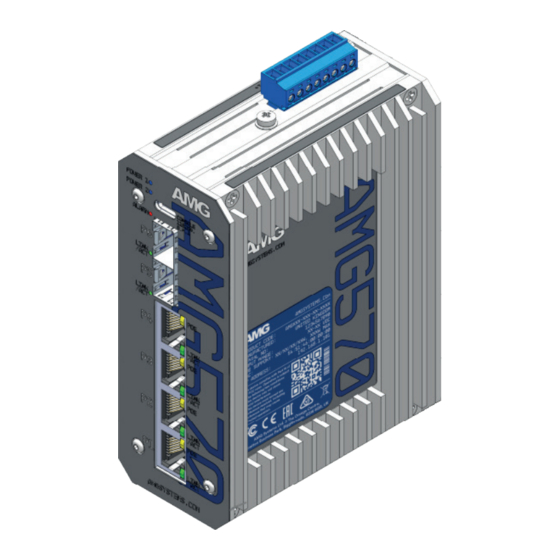
AMG570-4G-2S Series
AMG570-4G-2S Series
L2+ Industrial Managed Switch
L2+ Industrial Managed Switch
Installation Manual - Hardware
Installation Manual - Hardware
amgsystems.com
Advertisement

Related Manuals for AMG AMG570-4G-2S Series


Summary of Contents for AMG AMG570-4G-2S Series
- Page 1 QR code amg-support.com/AMG570-4G-2S_Series above or the direct link opposite. AMG Systems Ltd. 3 The Omega Centre, Stratton Business Park, Biggleswade, Bedfordshire, SG18 8QB, UK amgsystems.com T :: +44 (0) 1767 600 777 E :: sales@amgsystems.com...
- Page 2 AMG570-4G-2S INCLUDED ACCESSORIES DIN RAIL MOUNT INSTALLATION SURFACE MOUNT INSTALLATION ① Remove the DIN rail clip by unscrewing the two fixing screws as shown. USB Console Cable DIN Rail Bracket ② Attach the included wall mount brackets with the provided 4 x M3 screws as AMG570 Switch shown.
Need help?
Do you have a question about the AMG570-4G-2S Series and is the answer not in the manual?
Questions and answers