DeWALT DXAEC801B, DXAEC801BCA - 30A Bench Battery Charger with 80A Engine Start Manual
- Instruction manual (31 pages)
Advertisement
- 1 Introduction
- 2 Important Safety Instructions
- 3 Overview
- 4 Preparing to Charge
- 5 Charging the Battery
- 6 Indications and Faults
- 7 Reconditioning the Battery
- 8 Checking the Alternator
- 9 Starting the Engine
- 10 USB Port
- 11 AC Pass Through
- 12 Care and Maintenance
- 13 Troubleshooting
- 14 Accessories
- 15 Service Information
- 16 Specifications
- 17 Documents / Resources
Introduction
Engine Start
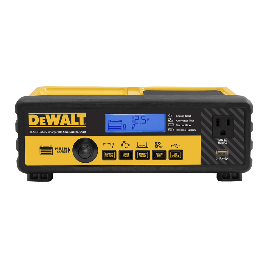
The DXAEC801B/DXAEC801BCA 30A Bench Battery Charger with 80A Engine Start is a DeWALT 30A battery charger that features 80A engine start, alternator check, and battery reconditioning functions; a USB port and an AC power outlet.
Definitions: Safety Guidelines
The definitions below describe the level of severity for each signal word. Please read the manual and pay attention to these symbols.

Indicates an imminently hazardous situation which, if not avoided, will result in death or serious injury.

Indicates a potentially hazardous situation which, if not avoided, could result in death or serious injury.

Indicates a potentially hazardous situation which, if not avoided, may result in minor or moderate injury.
NOTICE: Indicates a practice not related to personal injury which, if not avoided, may result in property damage.
Important Safety Instructions

Read all instructions before operating product. Failure to follow all instructions listed below may result in electric shock, fire and/or serious injury.
This product or its power cord contains lead, a chemical known to the State of California to cause cancer and birth defect or other reproductive harm. Wash hands after handling. For more information go to www.P65Warnings.ca.gov
- Keep these instructions.
- Heed all warnings.
- Follow all instructions.
- Avoid dangerous environments. Don't use battery chargers in damp or wet locations. Do not use the charger in the rain or snow.
- Clean only with a dry cloth.
- Keep children away from the charging area. Keep the charger away from children. This is not a toy!
- Store indoors. When not in use, battery chargers should be stored indoors in dry, and high or locked-up places – out of the reach of children.
- Unplug the battery charger when not in use.
- Stay alert. Use common sense. Do not operate this equipment when you are tired or impaired.
- Only use attachments/accessories specified by the manufacturer.
- Use only on a flat, level surface. If a cart is used, use caution when moving the cart/apparatus combination to avoid injury from tip-over.
![]()
- Check for damaged parts. Any part that is damaged should be properly repaired or replaced by manufacturer unless otherwise indicated elsewhere in this instruction manual before further use. Servicing is required when the apparatus has been damaged in any way, such as power-supply cord or plug is damaged, liquid has been spilled or objects have fallen into the apparatus, the apparatus has been exposed to rain or moisture, does not operate normally, or has been dropped. Contact the manufacturer at 1-888-394-3392 for more information.
- Apparatus shall not be exposed to dripping or splashing and no objects filled with liquids, shall be placed on the apparatus.

This Class B digital apparatus complies with Canadian ICES-003. CAN ICES-3(B).
Specific Safety Instructions for Power Cords
- Don't abuse the cord. Protect the power cord from being walked on or pinched particularly at plugs, convenience receptacles, and the point where they exit from the apparatus. Never carry the apparatus by cord or yank it to disconnect from receptacle. Keep the cord from heat, oil, and sharp edges. Pull by plug rather than cord when unplugging the unit.
- Ground fault circuit interrupter (GFCI) protection should be provided on the circuits or outlets to be used. Receptacles are available having built in GFCI protection and may be used for this measure of safety.

Never alter AC Power Cord or plug provided. If it will not fit the outlet, have a proper outlet installed by a qualified electrician. Improper connection can result in a risk of an electric shock.
Extension Cords
An extension cord should not be used unless absolutely necessary. Use of an improper extension cord could result in a risk of fire and electric shock, and will void warranty.
If an extension cord must be used, make sure your extension cord is in good condition. When using an extension cord, be sure to use one heavy enough to carry the current your product will draw. An undersized cord will cause a drop in line voltage resulting in loss of power and overheating. The following table shows the correct size to use depending on cord length and nameplate ampere rating. If in doubt, use the next heavier gauge. The smaller the gauge number, the heavier the cord.
Recommended Minimum AWG Size for Extension Cords for Battery Chargers
| AC Input Rating Amperes | American Wire Gage (AWG) Size of CordLength of Cord, feet (m) | ||||
| Equal to or greater than | But less than | 25 (7.6) | 50 (15.2) | 100 (30.5) | 150 (45.6) |
| 0 | 2 | 18 | 18 | 18 | 16 |
| 2 | 3 | 18 | 18 | 16 | 14 |
| 3 | 4 | 18 | 18 | 16 | 14 |
| 4 | 5 | 18 | 18 | 14 | 12 |
| 5 | 6 | 18 | 16 | 14 | 12 |
| 6 | 8 | 18 | 16 | 12 | 10 |
| 8 | 10 | 18 | 14 | 12 | 10 |
| 10 | 12 | 16 | 14 | 10 | 8 |
| 12 | 14 | 16 | 12 | 10 | 8 |
| 14 | 16 | 16 | 12 | 10 | 8 |
| 16 | 18 | 14 | 12 | 8 | 8 |
| 18 | 20 | 14 | 12 | 8 | 6 |
POWER CORD SAFETY
The battery charger is for use on a nominal 120 volt circuit, and has a grounding plug that looks like the plug illustrated in Figure A. A temporary adapter, which looks like the plug illustrated in Figures B and C may be used to connect this plug to a two-pole receptacle as shown in Figure B if a properly grounded outlet is not available. The temporary adapter should be used only until a properly grounded outlet can be installed by a qualified electrician.
Before using an adapter as shown in the following illustration, be certain that center screw of outlet plate is grounded. The green-colored rigid ear or lug extending from adapter must be connected to a properly grounded outlet – make certain it is grounded. If necessary, replace the original outlet cover plate screw with a longer screw that will secure the adapter ear or lug to outlet cover plate and make ground connection to a grounded outlet.

Specific Safety Instructions for Battery Chargers
Burst hazard: Do not use the unit for charging dry-cell batteries that are commonly used with home appliances. These batteries may burst and cause injury to persons and damage property. Use the unit for charging/boosting a 12 volt lead-acid battery only. It is not intended to supply power to a low-voltage electrical system other than in a starter-motor application.
- Use of accessories and attachments: The use of any accessory or attachment not recommended by manufacturer for use with this battery charger could be hazardous.
- Do not operate the battery charger near flammable liquids or in gaseous or explosive atmospheres. Motors may spark, and the sparks might ignite fumes.
To reduce the risk of electric shock, never immerse the battery charger in water or any other liquid, or use when wet.
Risk of explosive gases:
- Working in the vicinity of a lead acid battery is dangerous. Batteries generate explosive gases during normal battery operation. For this reason, it is of the utmost importance that each time before using the battery charger you read this manual and follow instructions exactly.
- To reduce the risk of battery explosion, follow these instructions and those published by the battery manufacturer and manufacturer of any equipment you intend to use in the vicinity of the battery. Review cautionary markings on these products and on the engine.
- This equipment employs parts (switches, relays, etc.) that produce arcs or sparks. Therefore, if used in a garage or enclosed area, the unit MUST be placed not less than 18 inches above the floor.
- THIS UNIT IS NOT FOR USE BY CHILDREN AND SHOULD ONLY BE OPERATED BY ADULTS.
To reduce the risk of fire:
- Do not operate near flammable materials, dust, fumes or gases.
- Do not expose to extreme heat or flames.
To reduce the risk of injury or property damage:
- NEVER ATTEMPT CHARGE A FROZEN BATTERY.
- Do not charge the battery while the engine is operating.
- Stay clear of fan blades, belts, pulleys, and other parts that can cause injury to persons.
- Vehicles that have on-board computerized systems may be damaged if vehicle battery is jump-started. Before jump-starting, read the vehicle's owner's manual to confirm that external-starting assistance is suitable.
- When working with lead acid batteries, always make sure someone is close enough to provide immediate assistance in case of accident or emergency.
- Always have protective eyewear when using this product: contact with battery acid may cause blindness and/or severe burns. Be aware of first aid procedures in case of accidental contact with battery acid.
- Have plenty of fresh water and soap nearby in case battery acid contacts skin.
- If battery acid contacts skin or clothing, wash immediately with soap and water for at least 10 minutes and get medical attention immediately.
- Never smoke or allow a spark or flame in vicinity of vehicle battery, engine or battery charger.
- Remove personal metal items such as rings, bracelets, necklaces and watches when working with a lead acid battery. A lead acid battery can produce a short circuit current high enough to weld a ring, or similar metal object, to skin causing a severe burn.
- Be extra cautious to avoid dropping a metal tool onto the battery. It might spark or short-circuit the battery or another electrical part, and that may cause an explosion.
- Never allow battery acid to come in contact with this apparatus.
- Do not operate this apparatus in a closed area or restrict ventilation in any way.
- Always turn the battery charger off by unplugging it when not in use.
- DO NOT OPEN THE BATTERY CHARGER — there are no user serviceable parts inside. Opening the battery charger will void manufacturer's warranty.
- Operate battery charger only as described in this Instruction Manual.
- Check battery charger and components periodically for wear and tear. Return to manufacturer for replacement of worn or defective parts immediately.
To reduce the risk of injury, follow these instructions and those published by the battery manufacturer and manufacturer of any equipment you intend to use with this unit. Review cautionary markings on this product and on engine.
Specific Safety Instructions for the USB Port
- Do not insert foreign objects into the USB Port.
- Do not attach USB hubs or more than one personal electronic device to the USB Port.
- Do not use this unit to operate appliances that require more than 3.1 amps in total to operate from the USB Port.
Specific Safety Instructions for the AC Pass Through
- Do not insert foreign objects into the AC Pass Through.
- Do not attach AC outlet taps or multi-outlet extension cords, or attach more than one electrical appliance to the AC Pass Through.
- Observe all Safety Instructions in the "Specific Safety Instructions for Power Cords" section of this Instruction Manual.
First aid
- Skin: if battery acid comes in contact with skin, rinse immediately with water, then wash thoroughly with soap and water. If redness, pain, or irritation occurs, seek immediate medical attention.
- Eyes: If battery acid comes in contact with eyes, flush eyes immediately, for a minimum of 15 minutes and seek immediate medical attention.
- LCD liquid crystal display: If liquid crystal comes in contact with your skin: Wash area off completely with plenty of water. Remove contaminated clothing. If liquid crystal gets into your eye: Flush the affected eye with clean water and then seek medical attention. If liquid crystal is swallowed: Flush your mouth thoroughly with water. Drink large quantities of water and induce vomiting. Then seek medical attention.
Overview
Front Panel Components

- LCD Screen
- AC Pass-Through
- Battery Charge Button
- Battery Voltage Button
- Engine Start Button
- Battery Recondition Button
- Alternator Check Button
- USB Power Button
- USB Port
- USB Power/Fault Indicator
Back Panel Components

- Padded Storage Tray
- High-Speed Cooling Fan
- Storage Tray
- Negative Clamp (black)
- Positive Clamp (red)
- AC Power Cord (bottom of apparatus)
- Fuse
- Fuse Holder
LCD Screen

- Battery Reconditioning Icons
- Battery Recondition Indicator
- High Temperature Compensation Icon
- Low Temperature Compensation Icon
- Digital Display (varies by function)
- Seconds/Voltage/Ampere/ Percentage Indicator
- USB Icon
- Fault Icon
- Alternator Good/Fault Indicators
- Alternator Icon
- Pump Engine Icon
- Overheat Alarm Icon
- Alarm Icon
- Clamp Icons
- Reverse Polarity Icons
- Battery Icon
Preparing to Charge
- Be sure the area around battery is well ventilated while the battery is being charged.
- Remove the battery completely from a boat/airplane or any confined area before charging.
- If it is necessary to remove battery from a vehicle to charge or to clean terminals, always remove the grounded terminal from the battery first. Make sure all accessories in the vehicle are turned off, so as not to cause an electrical arc.
- Clean the battery terminals, taking care to avoid getting corrosive material in your eyes.
- Add distilled water in each cell until battery acid reaches the level specified by the battery manufacturer. This helps purge excessive gas from cells. Do not overfill. For a battery without cell caps (maintenance free), carefully follow manufacturer's charging instructions.
- Study all battery manufacturer's specific precautions, such as removing or not removing cell caps while charging, and recommended rates of charge.
- Determine the voltage of the battery to be charged by referring to the vehicle manual. This unit is for charging a 12 volt battery only.
CHARGER LOCATION
- Locate the charger as far away from the battery as cables permit.
- Never place the charger directly above the battery being charged; gases from the battery will corrode and damage the charger.
- Never allow battery acid to drip on the charger when reading gravity or filling the battery.
- Never operate the charger in a closed-in area or restrict ventilation in any way.
- A marine (boat) battery must be removed and charged on shore. To charge it on board requires equipment specifically designed for marine use. This unit is NOT designed for such use.
- Do not set a battery on top of the charger.
CONNECTING THE CHARGER
 CONNECTION PRECAUTIONS
- Connect and disconnect output clamps only after removing AC Power Cord from electric outlet.
- Never allow the clamps to touch each other.
- Attach the clamps to the battery and chassis as indicated in the appropriate section ("Charging a battery installed in a vehicle" or "Charging a battery that has been removed from a vehicle").
FOLLOW THESE STEPS WHEN THE BATTERY IS INSTALLED IN A VEHICLE
A spark near the battery may cause an explosion. To reduce risk of a spark near the battery:
- Do not charge the battery while the engine is operating.
- Position AC and clamp cords to reduce risk of damage by hood, door, or moving engine part.
- Stay clear of fan blades, belts, pulleys, and other parts that can cause injury to persons.
- Check polarity of the battery posts. The positive post (marked POS, P, +) usually has a larger diameter than the negative battery post (marked NEG, N, –).
- Determine which post of battery is grounded (connected) to the chassis. If negative post is grounded to chassis (as in most vehicles), see 6. If positive post is grounded to the chassis, see 7.
- For a negative-grounded vehicle, connect the positive (red) clamp from the battery charger to the positive (POS, P, +) ungrounded post of battery. Connect the negative (black) clamp to vehicle chassis or engine block away from battery. Do not connect clip to carburetor, fuel lines, or sheet-metal body parts. Connect to heavy gauge metal part of the frame or engine block.
- For a positive-grounded vehicle, connect the negative (black) clamp from the battery charger to the negative (NEG, N, –) ungrounded post of battery. Connect positive (red) clamp to vehicle chassis or engine block away from battery. Do not connect clip to carburetor, fuel lines or sheet-metal body parts. Connect to a heavy gauge metal part of the frame or engine block.
- See operating instructions for length of charge information.
- When disconnecting charger, unplug the AC Power Cord, remove the clamp from vehicle chassis, and then remove the clamp from the battery terminal.
FOLLOW THESE STEPS WHEN THE BATTERY HAS BEEN REMOVED FROM A VEHICLE
A spark near the battery may cause an explosion. To reduce risk of a spark near the battery:
- Check polarity of the battery posts. The positive post (marked POS, P, +) usually has a larger diameter than the negative battery post (marked NEG, N, –).
- Attach a 24-inch (minimum length) AWG #6 insulated battery cable to the negative battery post (marked NEG, N, –).
- Connect the positive (red) clamp to the positive battery post (red or marked POS, P, +).
- Stand as far back from the battery as possible, and do not face the battery when making final connection.
- Carefully connect the negative (black) clamp to the free end of the battery cable connected to the negative terminal.
- When disconnecting the charger, always do so in reverse sequence of connecting procedure and break first connection while as far away from battery as practical.
Charging the Battery

If a problem is encountered during the battery charging process, refer to the "Indications and Faults" section that follows the battery charging directions.
- Connect the battery charger to the battery using the battery clamps, following the appropriate directions in the "Preparing to Charge" section of this Instruction Manual.
- Plug the unit's AC Power Cord into a functioning AC outlet.
![]()
If the battery clamps are not yet connected to a battery, a beep will sound and the LCD Screen will show the following (the empty Battery Icon will light solid):
![]()
- If the clamps are properly connected with regard to polarity, the LCD Screen will show the following, indicating the unit is in Standby Mode:
![]()
The Digital Display shows the voltage of the connected battery. The bars on the Battery Icon represent the charge level of the connected battery. The Clamp Icons and the Battery Icon light solid.
NOTE: In Standby Mode, the Digital Display shows the voltage (V) of the connected battery by default. Press the Battery Voltage Button once to show the charge status of the battery as a percentage (%) of full. Pressing the Voltage Button cycles through different standby status views of the connected battery.
![]()
If the battery clamps are connected incorrectly with regard to polarity, the LCD Screen shows the following:
![]()
The (empty) Battery Icon and the Clamp Icons light solid. The Alarm Icon, Reverse Polarity Icons, and the "+" and "–" signs on both the Clamp Icons and the Battery Icon flash. The unit emits a continuous warning sound until the clamps are disconnected. Remove the clamps and then reconnect the clamps properly. - When the clamps are connected correctly, press the Battery Charge Button. The LCD Screen will show the following:
![]()
The Digital Display shows the output current that is charging the battery. The Clamp Icons light solid and the bars on the Battery Icon will change from empty to solid (bottom to top) to indicate the unit is in Charging Mode.
NOTES:- If the battery is already charged to nearly full capacity, the unit's output current may be automatically reduced by a few amperes, despite the maximum output current rating of 30A.
- The charging process will start automatically approximately one minute after the unit is properly connected to a battery if no other actions are taken.
- The charging process can be terminated by pressing the Battery Charge Button again to stop the function. The unit will revert to the Standby Mode. It will automatically restart the charging process after approximately one minute if no other actions are taken.
- In Charging Mode, the Digital Display shows the output current (A) that is charging the battery by default. Press the Battery Voltage Button once to show the voltage (V) of the connected battery. Press the Battery Voltage Button again to show the charge status of the battery as a percentage (%) of full. Pressing the Voltage Button cycles through different charging status views of the connected battery.
- When the battery is completely charged, the unit automatically goes into Float Charge Mode. In this mode, the unit monitors the battery voltage and charges as necessary to assure the battery maintains a full charge. The unit remains in Float Charge Mode as long as the charger is connected to the battery and plugged into a functioning AC outlet. The LCD Screen shows the following:
![]()
The Digital Display shows "FLO" indicating that the unit is in Float Charge Mode. The Clamp Icons and the Battery Icon (with three bars) will light solid.
NOTE: In Float Charge Mode, the Digital Display shows "FLO" by default. Press the Battery Voltage Button once to show the voltage (V) of the connected battery. Press the Battery Voltage Button again to show the charge status of the battery as a percentage (%) of full. Pressing the Voltage Button cycles through different charging status views of the connected battery. - When disconnecting the battery charger, unplug the AC Power Cord, remove the clamp from the vehicle chassis, and then remove the clamp from the battery terminal.


Indications and Faults
| LCD Screen Shows: | Indication | Solution: |
 | Temperature Compensation Activated: The " " Icon will appear if the surrounding ambient temperature is higher than approximately 40°C. The " " Icon will appear if the surrounding ambient temperature is higher than approximately 40°C. The " " Icon will appear if the surrounding ambient temperature is lower than 0°C. This is not a fault code, but indicates that the unit's temperature compensation feature is operating. " Icon will appear if the surrounding ambient temperature is lower than 0°C. This is not a fault code, but indicates that the unit's temperature compensation feature is operating. | No user action is required. |
 | Overheat Protection Activated: If the charger is overheated, the charging process automatically terminates. The Fault Icon and the Overheat Alarm Icon flash. The (full) Battery Icon and Clamp Icons light solid. | Disconnect the connections and allow the charger to cool for several minutes. Make sure there is adequate ventilation around the unit before attempting to charge again. |
 | Battery Problem Detected: The charger automatically checks the battery condition 3 minutes after the charging process starts. If the charger detects a problem with a battery, the charging process automatically terminates. The Fault Icon and the (empty) Battery Icon flash. The Clamp Icons light solid. | Disconnect the connections. Have the battery checked by a qualified technician. |
 | Possible Battery Problem Detected: If the battery is not fully charged after 18 hours of continuous charging, the battery may have internal damage and will not accept a charge. After 18 hours, the charging process automatically terminates. The Digital Display shows "F04". The Fault Icon and the (empty) Battery Icon flash. | Disconnect the connections. Have the battery checked by a qualified technician. |
Reconditioning the Battery
Periodic reconditioning is recommended to maintain a battery's optimum performance. Battery recondition sends a series of electrical pulses to break up the crystalline form of lead sulfate and turn these chemicals into useful battery electrolytes.
- Refer to the "Charging the Battery" section of this Instruction Manual. Set up the battery charger and connect to the battery following steps 1 and 2. The unit will be in Standby Mode.
- Press the Battery Recondition Button once. A beep will sound and the Digital Display will show the following:
![]()
The Battery Recondition Indicator and the Battery Icon light solid. The Battery Recondition Icons flash, and the bars on the Battery Icon change from solid to empty (top to bottom) repeatedly.
The process stops automatically after 24 hours. To end the process sooner, press the Battery Recondition Button once again to turn it off. A beep will sound and the unit will return to Standby Mode. More than 24 hours may be needed to restore performance on some batteries. If so, repeat the process. - When disconnecting the battery charger, unplug the AC Power Cord, and then disconnect the battery charger from the battery following the last step in the "Preparing to Charge" section of this Instruction Manual.

If 5 cycles of reconditioning does not improve battery performance, discontinue and recycle the battery.
Checking the Alternator
PART 1
No Load (turn OFF all vehicle's accessories): The vehicle battery must be fully charged before testing the alternator. Run the engine long enough to achieve normal idle speed and verify there is a no-load voltage.
- Refer to the "Charging the Battery" section of this Instruction Manual. Set up the battery charger and connect to the battery following steps 1 and 2. The unit will be in Standby Mode.
- Press the Alternator Check Button to start the check. The Digital Display shows the following to indicate the unit is analyzing the alternator:
![]()
The Alternator Icon will flash and the Battery icon with two bars will light solid. - If the unit detects that the selected alternator is good, the LCD Screen shows the following:
![]()
The Alternator Icon, "ALT GOOD" and the FULL Battery Icon will light solid. - If the unit detects that the selected alternator is out of typical voltage range, the LCD Screen shows the following:
![]()
The Fault Icon will flash. The Alternator Icon, "ALT" and the (empty) Battery Status Icon will light solid. - Press the Alternator Check Button again to stop the check.


PART 2
Under Load (accessories ON): Next, load the alternator by turning on as many accessories as possible (except for the A/C and Defrost).
- Refer to the "Charging the Battery" section of this Instruction Manual. Set up the battery charger and connect to the battery following steps 1 and 2. The unit will be in Standby Mode.
- Press the Alternator Check Button to start the check. The Digital Display shows the following to indicate the unit is analyzing the alternator:
![]()
The Alternator Icon will flash and the Battery icon with two bars will light solid. - If the unit detects that the selected alternator is good, the LCD Screen shows the following:
![]()
The Alternator Icon, "ALT GOOD" and the FULL Battery Icon will light solid. - If the unit detects that the selected alternator is out of typical voltage range, the LCD Screen shows the following:
![]()
The Fault Icon will flash. The Alternator Icon, "ALT" and the (empty) Battery Status Icon will light solid. - Press the Alternator Check Button again to stop the check.
- When disconnecting the battery charger, unplug the AC Power Cord, and then disconnect the battery charger from the battery following the last step of the directions in the "Preparing to Charge" section of this Instruction Manual.
Notes Concerning the Alternator Check Function:
![]()
This check may not be accurate for every make, manufacturer and model of vehicle. Check only 12 volt systems.- The unit may detect that the alternator is out of typical voltage range because someone has added a number of accessory loads on the charging system, thereby increasing current demand from the alternator. MAKE SURE THAT THE ALTERNATOR IS RATED TO SUPPORT THE APPLICATION.
Starting the Engine
- Refer to the "Charging the Battery" section of this Instruction Manual. Set up the battery charger and connect to the battery following steps 1 and 2. The unit will be in Standby Mode.
- Press the Engine Start Button once. A beep will sound and the LCD Screen shows the following:
![]()
The Digital Display shows the countdown from "60" to "0" to indicate the unit is in Engine Start Mode. The bars on the Battery Icon will change from empty to solid (bottom to top) repeatedly. The Clamp Icons and the Battery Icon will light solid.
NOTES:- The Engine Start function may not be started if the battery charger detects that the battery is at full capacity (fully charged).
- The Engine Start countdown process can be terminated by pressing the Engine Start Button again to stop the function.
- When "0" is reached, a beep will sound and the LCD Screen will show the following:
![]()
The Pump Engine Icon will light solid and the Digital Display shows "0 SEC" to indicate the vehicle is ready to start. The Clamps Icon and the Battery Icon light solid. - Crank the engine using manufacturer's guidelines, typically in 3 to 5 second bursts. The Digital Display shows "5 SEC" (a 5-second countdown to use as a timer when cranking the engine).
- After cranking, the unit will automatically adjust the charging current to 7.5A for 5 minutes, and then revert to Charging Mode. To stop charging, press the Battery Charge Button.
![]()
The Engine Start function requires a resting/cooling period between attempts. Wait 4 to 5 minutes before a second attempt at starting the engine, if needed. - When disconnecting the battery charger, unplug the AC Power Cord, and then disconnect the battery charger from the battery following the last step of the directions in the "Preparing to Charge" section of this Instruction Manual.


USB Port
The USB Power Button and the USB Port are located on the front of unit. The USB Power/Fault Indicator is a translucent ring around the USB Port. Refer to Fig. 1 to locate.
Important Notes Concerning the USB Port
- This unit's USB Port does not support data communication. It only provides power to an external USB-powered device. The USB Port provides up to 3.1A (5V).
- When the USB Port is in use, the unit will monitor for the following USB fault conditions: thermal fault, overload and short circuit. If a fault condition exists the USB Power/Fault Indicator will flash blue. In any of these cases, the LCD screen will continuously display the following:
![]()
The USB Icon and the Fault Icon will flash. The USB Port will automatically shut down. Should this occur:- Disconnect the USB-powered device and press the USB Power Button again to turn off the USB Port immediately.
- Allow the unit to cool down for several minutes before attempting to use the USB Port again.
- If a fault occurs again, make sure that the draw of the USB device plugged into the USB Port does not exceed 3.1A.
- If an individual USB device is within specifications and the fault occurs, have the USB device checked for malfunction and do not continue to use it with this USB Port.
- Some household USB-powered electronics will not operate with this unit.

USING THE USB PORT
- Plug the battery charger's AC Power Cord into a functioning AC outlet. A beep will sound and the LCD Screen will show the following:
![]()
The (empty) Battery Icon will light solid to indicate the built-in Battery Clamps are not yet connected to the battery. - Press the USB Power Button to turn on the USB Port. A beep will sound, the USB Power/Fault Indicator around the USB Port will light blue and the LCD Screen will continuously display the following:
![]()
The USB Icon will light solid, indicating the USB port is ready to use. - Plug the USB-powered device into the USB power port and operate normally.
- Press the USB power button again to turn off the USB Port.


AC Pass Through
This unit features a 120V AC Pass Through. When using this feature, follow all instructions and warnings found in the "Specific Safety Instructions for the AC Pass Through" in the front of this Instruction Manual.
NOTE: The 120V AC Pass Through is protected by a fuse located on the back of the unit (see Fig. 2). If the 120V AC Pass Through shuts down when it is in use, this fuse may have blown. Refer to the "Maintenance" and "Troubleshooting" sections for more information.
Care and Maintenance
To reduce the risk of electric shock, unplug the battery charger from the outlet before attempting any maintenance or cleaning.
Turning off the controls will not reduce this risk.
CLEANING AND STORAGE
- Store the unit in a clean, dry, cool place when not in use.
- Clean the unit casing and cords (as necessary) with a dry cloth. Ensure that unit is completely disconnected from battery and power source before cleaning.
- Do not immerse the appliance in water.
- To maintain the operating condition and maximize the life of the charger cords, always coil them loosely on the built-in storage spool when not in use. Do not wrap them around the unit or crimp them with a tight band.
REPLACING THE 120V AC PASS THROUGH FUSE
The fuse that protects the AC Pass-Through circuit is located on the back of the unit (see Fig. 2) within the Fuse Holder. The Fuse Holder features a groove to allow locking or unlocking using a small coin or screwdriver.
NOTE: Remove the clamps from the clamp holders before proceeding with the fuse replacement procedure.
- Use a coin, screwdriver, or other appropriate tool. Align it and push it forward into the groove of the Fuse Holder, then slightly rotate it counterclockwise about 90 degrees until the Fuse Holder is automatically released.
- Remove the fuse from the Fuse Holder and check it with a continuity checker.
- If the Fuse is blown, locate a replacement 6A fuse.
- Replace the Fuse into the Fuse Holder.
- Replace the Fuse Holder by placing it back in position. Then use a coin, screwdriver, or other appropriate tool aligned in the groove of the Fuse Holder, to push it forward, and then slightly rotate it clockwise about 90 degrees until the Fuse Holder locks back into the unit. Do NOT overtighten.
Troubleshooting
| Problem | Possible Solution |
| Unit fails to turn on | Check that the charger is properly connected to a live 120 volt AC outlet. |
| Unit fails to charge | Check that the charger is properly connected to a live 120 volt AC outlet. |
| If the battery to be charged has fallen below 2 volts, the battery cannot be recharged with this charger. | |
| Make sure a proper polarity cable connection has been established. | |
| AC Pass Through will not power appliance | Check that the battery charger is properly connected to a live 120 volt AC Outlet. |
| Make sure the appliance is properly connected to the AC Pass Through and that the appliance is turned on. | |
| Mark sure that the total draw of the AC appliance connected to the AC Pass Through does not exceed 700W. | |
| Check that the fuse inside the fuse holder at the back of the unit is not blown. Replace the fuse with the same type and size (250V / 6A) if it is blown. | |
| USB Port will not power appliance | Make sure the USB Power Button has been turned on. |
| Make sure the USB Power/Fault Indicator lights solid blue. If a fault condition exists in the USB Port, the USB Power/Fault Indicator will flash blue. Refer to the Important Notes in the "Using the USB Port" section to remedy any faults. | |
| Make sure that the draw of the USB device plugged into the USB Port does not exceed 5V/3.1A. | |
| Some USB-powered household electronics will not operate with this USB charging/ power port. Check the manual of the corresponding electronic device to confirm that it can be used with this type of USB charging/power port. |
Accessories
Since accessories, other than those offered by DeWALT, have not been tested with this product, use of such accessories with this unit could be hazardous. To reduce the risk of injury, only DeWALT recommended accessories should be used with this product.
If you need assistance regarding accessories, please contact Baccus at 1-888-394-3392 or CustomerService@dewalt12volt.com.
Service Information
Whether you need technical advice, repair, or genuine factory replacement parts, please contact Baccus at 1-888-394-3392 or CustomerService@dewalt12volt.com.
Product Registration
Please complete the Product Registration Card and return within 30 days from purchase of the product to: Baccus Global LLC, 621 NW 53rd St., Suite 450, Boca Raton, FL 33487. Baccus Global LLC, toll-free number: 1-888-394-3392. www.dewalt12volt.com.
Specifications
| Input | 120V AC, 60Hz, 1220W (Battery Charger: 520W; AC Pass-Through Output: 700W) |
| Output | 12V DC, 30A, 80A Engine Start (5 seconds ON, 5 minutes OFF) |
| USB Output | 5V DC, 3.1A max. |
Manufactured and Imported by Baccus Global LLC,
621 NW 53rd St., Suite 450, Boca Raton, FL 33487
www.dewalt12volt.com
1-888-394-3392

Documents / Resources
References

Download manual
Here you can download full pdf version of manual, it may contain additional safety instructions, warranty information, FCC rules, etc.
Download DeWALT DXAEC801B, DXAEC801BCA - 30A Bench Battery Charger with 80A Engine Start Manual
Advertisement


Need help?
Do you have a question about the DXAEC801B and is the answer not in the manual?
Questions and answers