Table of Contents
Advertisement
Quick Links
Quark Overdrive
Maxon OD-880 Overdrive / Soft Distortion
Overview
Controls & Usage
The OD-880's controls are as simple as they come:
• Sensitivity controls the amount of gain in the op amp stage that is later hard-clipped.
• Level controls the overall output.
Modifications & Experimentation
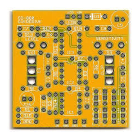
The Clipping switch mod allows you to set up a second set of diodes to toggle back and forth from stock.
Extra pads have been provided so you can stack two diodes in a row if desired. (The middle two pads are
connected in each diode.) If you use a SPDT center-off switch, the middle position becomes a diode lift mode,
but you can also use a regular SPDT if you don't care about this.
The EQ switch changes the tone stack from stock to modded. The biggest criticism of this circuit is that it cuts
too much bass, so this mod gives more bass and fullness and changes the overall gain structure of the effect.
Note that this mod doesn't have an "off" mode like a clipping switch or a capacitor mod would, so don't use a
center-off switch here. Just use a normal two-position SPDT.
The original uses a few LM741 op amps. These are fine, and the comparatively low fidelity of these op amps
is part of the sound, like in the Distortion+. However, if you want to experiment, you can swap in any single op
amp here such as a TL061/TL071, CA3130EZ/CA3140EZ, or a NE5534.
MAXON OD-880 / QUARK OVERDRIVE
The Quark Overdrive is a clone of the Maxon OD-880 Overdrive
/ Soft Distortion, originally released in 1976. This pedal was huge
in Japan, being the favored overdrive pedal of Char, one of the
country's most popular guitarists, who—like the pedal—never
really got noticed out of Japan. It was reissued a few times,
notably in the mid-90's as well as in the past couple of years.
It's an interesting circuit from a historical perspective, being
sort of a "transitional species" between the Distortion+ and the
Boss OD-1 OverDrive: it added the input and output buffers and
changed the Drive potentiometer to a flat op-amp boost instead
of a gain modifier that also affected the bass tone, like in the
Dist+. The OD-1 is essentially an OD-880 with feedback clipping
diodes instead of diode-to-ground clipping, though this diode
arrangement turned out to be a very big deal and made way for
the Tube Screamer a couple of years later.
1
Advertisement
Table of Contents

Summary of Contents for Aion Electronics Quark Maxon OD-880
- Page 1 Quark Overdrive Maxon OD-880 Overdrive / Soft Distortion Overview The Quark Overdrive is a clone of the Maxon OD-880 Overdrive / Soft Distortion, originally released in 1976. This pedal was huge in Japan, being the favored overdrive pedal of Char, one of the country’s most popular guitarists, who—like the pedal—never really got noticed out of Japan.
- Page 2 Parts Resistors Capacitors Semiconductors IC1–IC3 LM741P 470k 1N4002 D3, D4 1N914 100n D2, D5 jumper 470k 100n D5–8 1N914 100R 5mm LED 100k 100n 100n Potentiometers 47uF electro Sensitivity 500kB 10uF electro Level 10kB 220n 100k Other Clip SPDT center off SPDT 1M to 2M2 LEDR...
- Page 3 Schematic MAXON OD-880 / QUARK OVERDRIVE...
- Page 4 General Build Instructions These are general guidelines and explanations for all Aion Electronics DIY projects, so be aware that not everything described below may apply to this particular project. Build Order When putting together the PCB, it’s recommended that you do not yet solder any of the enclosure-mounted control components (pots and switches) to the board.
- Page 5 Drilling & Placement Print this page and have an adult cut out the drilling template below for you. Tape it to the enclosure to secure it while drilling. Note that the holes are shown slightly smaller than they need to be, so drill out the holes as shown and then step up until they are the correct size for the components.
- Page 6 Standard Wiring Diagram This diagram shows standard true-bypass wiring with a 3PDT switch. When the switch is off, the input of the circuit is grounded and the input jack is connected directly to the output jack. The SW pad is the cathode connection for the LED.


Need help?
Do you have a question about the Quark Maxon OD-880 and is the answer not in the manual?
Questions and answers