Table of Contents
Advertisement
Quick Links
This is a safety alert symbol and should never be ignored. When you see this symbol on labels or in
manuals, be alert to the potential for personal injury or death.
This unit has a delay relay that delays the supply blower "ON" for 1 second and keeps the blower "ON" for 45
seconds on all fan and cooling demands. For more details, refer to page 18 for unit sequence of operation.
Manufactured By
Blue Summit LLC
8201 C National Turnpike
Louisville, KY 40214
507787-01B
INSTALLATION INSTRUCTIONS
BE5C Series Air Handler
This manual must be left with the homeowner for future reference.
IMPORTANT INFORMATION FOR INSTALLER
2
1
1
SECOND
COOLING
DELAY
DEMAND
Save these instructions for future reference
BE5C Unit Dimensions - Upflow - Inches (mm) .........2
Shipping and Packing List ...........................................3
General ........................................................................3
Requirements ..............................................................3
Installation Clearances ................................................4
Installation ...................................................................4
Condensate Drain........................................................7
Duct System and Filters ..............................................8
Brazing Refrigerant Lines ............................................9
Sealing the Unit .........................................................12
Electrical Connections ...............................................12
Air Flow - Cooling Blower Speed ..............................16
Check-Out Procedures ..............................................18
Operation ...................................................................18
Homeowner Maintenance..........................................19
Repairing or Replacing Cabinet Insulation ................19
Professional Maintenance .........................................20
Use of Air Handler During Construction.....................20
3
4
100%
100%
CFM
CFM
45
SECS
Issue 1913
Table of Contents
OFF
*P507787-01B*
(P) 507787-01B
Page 1 of 22
Advertisement
Table of Contents

Related Manuals for Blueridge BE5C Series


Summary of Contents for Blueridge BE5C Series
-
Page 1: Table Of Contents
INSTALLATION INSTRUCTIONS BE5C Series Air Handler This manual must be left with the homeowner for future reference. This is a safety alert symbol and should never be ignored. When you see this symbol on labels or in manuals, be alert to the potential for personal injury or death. -
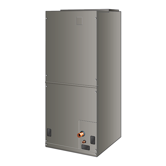
Page 2: Be5C Unit Dimensions - Upflow - Inches (Mm)
BE5C Unit Dimensions – Upflow – Inches (mm) 1 (25) DETAIL OF PIPING PLATE 4-3/4 3/4 (19) (121) SUCTION LINE SUPPLY AIR LIQUID OPENING CONDENSATE LINE 14-1/2 DRAINS (2) (368) 2-3/8 (Horizontal) (60) 1 (25) 1 (25) CONDENSATE DRAINS (2) 4-3/8 (Upflow and (111) -
Page 3: Shipping And Packing List
Conditioning and Ventilation Systems” (NFPA No. 90A) and “Standard for Installation of Residence Type Warm Air The BE5C series air handler with all-aluminum coil is Heating and Air Conditioning Systems” (NFPA No. 90B). designed for indoor installation only. As shipped, the unit All models are designed for indoor installation only. -
Page 4: Installation Clearances
Do not remove the cabinet knockouts until it has been • Electrical wires should be sealed on the inside where determined which knockouts will need to be removed for they exit the conduit opening. Sealant is required to the installation. prevent air leakage into, and condensate from forming inside of, the air handler, the control box, and on the Select the air discharge position which best suits the site... - Page 5 Upflow Application Right-Hand Discharge The air handler must be supported on the bottom only 1. Determine which plugs are required for drain line and set on solid floor or field-supplied support frame. connections. Securely attach the air handler to the floor or support With access door removed, remove drain line plugs to frame.
- Page 6 NOTE: Be very careful when reinstalling the screws into the coil end plate engaging holes. Misaligned IMPORTANT screws may damage the coil. After removal of drain pan plug(s), check drain hole(s) From the upflow position, flip cabinet 90º to the left to verify that drain opening is fully open and free of any and set into place.
-
Page 7: Condensate Drain
Sloping The Unit Condensate Drain Make sure the unit is sloped (similar to the slope shown in Figure 6) so that the drain pan will empty completely without water standing in the pan. IMPORTANT THIS CORNER SHOULD BE 5/8" (+/- 1/8") HIGHER On units of this type, where the blower “draws”... -
Page 8: Duct System And Filters
Install Condensate Drain NOTE: Do not operate air handler without a trap in the main (primary) drain. The condensate drain is on The air handler is provided with 3/4” NPT condensate drain the negative pressure side of the blower; therefore, air connections. -
Page 9: Brazing Refrigerant Lines
Brazing Refrigerant Lines IMPORTANT Refrigerant lines must be connected by a qualified If a high efficiency filter is being installed as part of this technician in accordance with established procedures. system to ensure better indoor air quality, the filter must be properly sized. - Page 10 NOTE: Recommended line length is 50’ or less. If more than 50’ line set is required, contact Blue Summit. CAUTION Route the suction and liquid lines from the fittings on Brazing alloys and flux contain materials which are the indoor coil to the fittings on the outdoor unit. Run hazardous to your health.
- Page 11 REMOVE ACCESS PANEL REMOVE RUBBER PLUG FROM BOTH LIQUID AND SUCTION LINES NOTE - BE5C SERIES UNITS USE NITROGEN OR DRY AIR PIPING AS A HOLDING CHARGE. IF THERE IS NO PRESSURE WHEN PLATE THE RUBBER PLUGS ARE REMOVED, CHECK THE COIL FOR LEAKS BEFORE INSTALLING.
-
Page 12: Sealing The Unit
Sealing the Unit WARNING Seal the unit so that warm air is not allowed into the cabinet. Electric Shock Hazard. Can cause injury or Warm air introduces moisture, which results in water blow- death. Unit must be properly grounded in off problems. - Page 13 • Separate openings have been provided for 24V low voltage and line voltage. Refer to the dimension illustration of specific location. • This unit is provided with holes for conduit. Use provided caps to seal holes not used. • Typical unit wiring (as well as wiring of optional field- installed electric heat) is given in Figure 14.
- Page 14 Figure 14. Typical Wiring Diagram – BE5C Air Handler with Electric Heat – PSC (018, 024, 030, 036, 042 models) Page 14 of 22 Issue 1913 507787-01B...
- Page 15 Figure 15. Typical Wiring Diagram – BE5C Air Handler with Electric Heat – CT (048 and 060 models) 507787-01B Issue 1913 Page 15 of 22...
-
Page 16: Air Flow - Cooling Blower Speed
THERMOSTAT AIR HANDLER THERMOSTAT AIR HANDLER NOTE NOTE HEAT ONLY APPLICATION CONDITIONER THERMOSTAT HEAT PUMP UNIT UNIT AIR HANDLER COOLING ONLY APPLICATION THERMOSTAT AIR HANDLER CONNECT COMMON WIRE ONLY IF REQUIRED (REFER TO THE APPROPRIATE THERMOSTAT INSTALLATION INSTRUCTIONS) NOTE HEAT PUMP APPLICATION WITH AIR CONDITIONER ELECTRIC HEAT UNIT... - Page 17 BLOWER RELAY PLASTIC CAPS NOTE - Refer to wiring diagram located on the BLOWER RELAY unit HARNESS ance (table 2). BLUE (MED) RED (L0) All air data measured external to unit with 1 inch non-pleated air filter in place. BLACK (HI) All factory settings are medium speed.
-
Page 18: Check-Out Procedures
Check Electric Heat (If Used) Check-Out Procedures 1. Set thermostat to call for auxiliary heat (approximately 5°F above ambient temperature). The indoor blower NOTE: Refer to outdoor unit installation instructions for and auxiliary heat should come on together. Allow a system start-up instructions and refrigerant charging minimum of 3 minutes for all sequencers to cycle on. -
Page 19: Homeowner Maintenance
Heating (Heat Pump) Repairing or Replacing Cabinet Insulation When the thermostat calls for heating, 24 volts is applied to the blower time-delay relay coil. Then, normally open contacts close, causing the indoor blower motor to operate. The circuit between R and Y is completed, closing IMPORTANT the circuit to the contactor in the outdoor unit, starting the DAMAGED INSULATION MUST BE REPAIRED OR... -
Page 20: Professional Maintenance
Professional Maintenance Use of Air Handler During Construction It is not recommended to use this air handler unit during any phase of construction. Very low return air temperatures, NOTICE harmful vapors and operation of the unit with clogged or Failure to follow instructions will cause damage to the misplaced filters will damage the unit. - Page 21 Installing Contractor’s Name_______________________ Installing Date_______________________________ Installing Contractor’s Phone_______________________ Air Handler Model #___________________________ Job Address____________________________________ Thermostat Line Voltage SUPPLY Disconnect Switch Temperature Integrated Control Duct Blower Motor Amps System Electric Heat Amps Duct Static RETURN Filter Drain Line DUCT SYSTEM TOTAL EXTERNAL STATIC (dry coil) dry coil wet coil SUPPLY AIR DUCT...
- Page 22 Installing Contractor’s Name_______________________ Installing Date_______________________________ Installing Contractor’s Phone_______________________ Air Handler Model #___________________________ Job Address____________________________________ Line Voltage Disconnect Switch Thermostat Integrated Control Duct System Duct System Filter RETURN SUPPLY Electric Heat Amps Blower motor Amps Drain Line Duct Static Temperature DUCT SYSTEM TOTAL EXTERNAL STATIC (dry coil) dry coil wet coil...
Need help?
Do you have a question about the BE5C Series and is the answer not in the manual?
Questions and answers