
Related Manuals for Blueridge BM12M22CNS


Summary of Contents for Blueridge BM12M22CNS
- Page 1 Installation Manual Low-wall air handler Model BM12M22CNS IMPORTANT NOTE: Read this manual carefully before installing or operating your new air conditioning unit. Make sure to save this manual for future reference.
-
Page 3: Table Of Contents
Table of Contents Installation Manual Accessories ..............Safety Precautions ..........Installation Summary - Indoor Unit ..Indoor Unit Installation ........Indoor Unit Parts ............07 Indoor Unit Installation Instructions ....08 Drainpipe Installation ......... Refrigerant Piping Connection ....Note on Pipe Length .......... Connection Instructions ........ -
Page 4: Accessories
Accessories The air conditioning system comes with the following accessories. Use all of the installation parts and accessories to install the air conditioner. Improper installation may result in water leakage, electrical shock and fire, or equipment failure. Name Name Shape Quantity Refrigeration Fittings Soundproof / insulation sheath (some models) -
Page 5: Safety Precautions
Safety Precautions Read Safety Precautions Before Installation Incorrect installation due to ignoring instructions can cause serious damage or injury. WARNING CAUTION. The seriousness of potential damage or injuries is classified as either a Failure to observe a warning may result in death. The appliance must be installed in accordance with national regulations. -
Page 6: Installation Summary - Indoor Unit
Installation Summary - Indoor Unit INSTALLATION ORDER Install the indoor unit Install the outdoor unit Install the drainpipe (Page 7) (Separate Manual) (Page 12) Connect the wires Connect the refrigerant (Page 17) pipes (Page 14) Revised 5/14/2020 Page 6 ... -
Page 7: Indoor Unit Installation
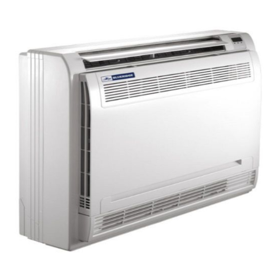
Indoor Unit Installation Indoor Unit Parts Air flow louver (at air outlet) Display panel Air inlet (with air filter in it) Air flow louver (at air outlet) Refrigerant connecting pipe Drain hose Fig. 4.1 Safety Precautions WARNING CAUTION • Securely install the indoor unit on a •... -
Page 8: Indoor Unit Installation Instructions
Indoor Unit Installation Instructions CAUTION DO NOT install the unit in the following NOTE: Panel installation should be performed locations: after piping and wiring have been completed. Areas with oil drilling or fracking Step 1: Select installation location Coastal areas with high salt content in the The indoor unit should be installed in a location that meets the following requirements: Areas with caustic gases in the air, such as... - Page 9 Hook Fig. 4.3 Revised 5/14/2020 Page 9 ...
- Page 10 Step 2: Installing the main body • Affix the hook with a tapping screw onto the wall. Hook Tapping screw Washer Fig. 4.4 • Hang the indoor unit on the hook. (The bottom of body can touch the floor or remain suspended, but the body must be installed vertically.) Fig.
- Page 11 Step 3: Taking the indoor unit apart to connect 3. Remove the face plate the pipes Remove the four screws. (See Fig.4.7) Open the bottom of the face plate at a 30-de- 1. Open the front panel gree angle. Lift the top of the face plate. (See Slide the two stoppers on the left and right Fig.4.8) sides inward until they click.
-
Page 12: Drainpipe Installation
Drainpipe Installation The drainpipe is used to drain water away from the unit. Improper installation may cause unit and property damage. CAUTION • Insulate all piping to prevent condensation, which could lead to water damage. • If the drainpipe is bent or installed incorrectly, water may leak and cause a Lean over 1/100 water-level switch malfunction. - Page 13 3. Using a 2.5” hole saw drill, drill a hole in the NOTE: When drilling the hole, make sure to wall. Make sure that the hole is drilled at a avoid wires, plumbing, and other sensitive slight downward angle, so that the outdoor components.
-
Page 14: Refrigerant Piping Connection
Refrigerant Piping Connection Note on Pipe Length The length of refrigerant piping will affect the performance and energy efficiency of the unit. Nominal efficiency is tested on units with a pipe length of 16.5ft. In North America, standard pipe length is 25’. A minimum pipe run of 10 feet is required to minimize vibration &... - Page 15 2. Using a pipe cutter, cut the pipe a little longer Flare nut than the measured distance. 3. Make sure that the pipe is cut at a perfect 90° angle. Refer to Fig. 6.1 for bad cut examples. Copper pipe 90°...
- Page 16 Note: Use of an approved refrigerant sealant is 6. Place flaring tool onto the form. recommended for all flare joint connections. 7. Turn the handle of the flaring tool clockwise until the pipe is fully flared. Instructions for Connecting Piping to 8.
-
Page 17: Wiring
Wiring BEFORE PERFORMING ANY ELECTRICAL WORK, READ THESE REGULATIONS 1. All wiring must comply with local and national electrical codes, regulations and must be installed by a licensed electrician. 2. All electrical connections must be made according to the Electrical Connection Diagram located on the panels of the indoor and outdoor units. - Page 18 Indoor Unit Wiring 1. Prepare the cable for connection. 3. Connect the u-lugs to the terminals. Match the wire colors/labels with the labels a. Using wire strippers, strip the rubber jacket on the terminal block. Firmly screw the u-lug from both ends of the signal cable to reveal of each wire to its corresponding terminal.
- Page 19 Install Outdoor Unit (see separate manual) When you have finished installing all indoor air handlers, proceed to installation of the outdoor unit. Complete installation instructions and startup procedures are given in the outdoor unit installation manual. Copies are always available at AlpineHomeAir.com by searching your unit's model number and scrolling to Documents.
- Page 20 The design and specifications are subject to change without prior notice for product improvement. AlpineHomeAir.com...
Need help?
Do you have a question about the BM12M22CNS and is the answer not in the manual?
Questions and answers