Table of Contents
Advertisement
Quick Links
Save these instructions for future use!
FAILURE TO READ AND FOLLOW ALL INSTRUCTIONS
CAREFULLY BEFORE INSTALLING OR OPERATING THIS
CONTROL COULD CAUSE PERSONAL INJURY AND/OR
PROPERTY DAMAGE.
THERMOSTAT APPLICATION GUIDE
Thermostat
Configuration Options
Gas, Oil, Electric, Heat Only,
Single Stage 1
Cool Only or Heat/Cool
No Heat Pump (SS1)
Systems, 2 or 3 wire Hydronic
Multi Stage 2
Zone (Hot Water or Steam)
No Heat Pump (MS2)
Systems, 24 Volt or Millivolt
Heat Pump 1
Single Stage Compressor
Single Stage Compressor
Heat Pump Systems - up to 2
Heat Pump (HP1)
Stages Aux./Emergency Heat
Heat Pump 2
Two Stage or Two Compressor
Two Stage or Two
Heat Pump systems - up to 2
Compressor Heat Pump
Stages Aux./Emergency Heat
(HP2)
Electrical Rating:
Battery Power . . . . . . . . . . . . . . . . . . . . . . . . . . mV to 30 VAC, NEC Class II, 50/60 Hz or DC
Input-Hardwire . . . . . . . . . . . . . . . . . . . . . . . . . 20 to 30 VAC
Terminal Load . . . . . . . . . . . . . . . . . . . . . . . . . . . . . 1.5A per terminal, 2.5A maximum all terminals combined
Setpoint Range . . . . . . . . . . . . . . . . . . . . . . . . . . . . 45 to 99°F (7 to 37°C)
Rated Differentials:
Heat (Single Stage/Multi-Stage) . . . . . . . . . . . .
Cool (Single Stage/Multi-Stage) . . . . . . . . . . . .
Heat Pump . . . . . . . . . . . . . . . . . . . . . . . . . . . .
Emer Heat . . . . . . . . . . . . . . . . . . . . . . . . . . . .
Operating Ambient. . . . . . . . . . . . . . . . . . . . . . . . . . 32°F to +105°F (0 to +41°C)
Operating Humidity . . . . . . . . . . . . . . . . . . . . . . . . . 90% non-condensing max.
Shipping Temperature Range . . . . . . . . . . . . . . . . . -40 to +150°F (-40 to +65°C)
Dimensions Thermostat. . . . . . . . . . . . . . . . . . . . . . 4-9/16"H x 5-13/16"W x 1-3/16"D
CAUTION
!
To prevent electrical shock and/or equipment damage,
disconnect electric power to system at main fuse or
circuit breaker box until installation is complete.
Index
Installation
Wiring Diagrams
Thermostat Quick Reference
Installer Configuration Menu
Operating Your Thermostat
Programming
Troubleshooting
Blue Universal Touchscreen Thermostat with
Automatic Heat/Cool Changeover Option
Maximum
Thermostat
Stages
Applications
Heat/Cool
1+1
2+2
3+1
4+2
Page
2
3
4
5
9
10
13
Single Stage, Multi-Stage, Heat Pump
Installation and Operating Instructions
Model
Programming Choices
OH-1202
7 Day
5+1+1 Day
Touchscreen Thermostat
Fast.
Slow
0.6°F
1.5°F
1.2°F
1.7°F
1.2°F
1.7°F
0.6°F
1.7°F
ATTENTION: MERCURY NOTICE
This product does not contain mercury. However, this
product may replace a product that contains mercury.
Mercury and products containing mercury must not be
discarded in household trash. Do not touch any spilled
mercury. Wearing non-absorbent gloves, clean up any
spilled mercury and place in a sealed container. For proper
disposal of a product containing mercury or a sealed
container of spilled mercury, place it in a suitable shipping
container. Refer to www.thermostat-recycle.org for
location to send the product containing mercury.
WARNING
!
For California Residents: This product contains a
chemical known to the state of California to cause
cancer and birth defects and other reproductive harm.
Non-Programmable
APPLICATIONS
SPECIFICATIONS
PART NO. 37- 7403B
Replaces 37-7403A
1639
Advertisement
Table of Contents

Related Manuals for Emerson OH-1202


Summary of Contents for Emerson OH-1202
- Page 1 Save these instructions for future use! FAILURE TO READ AND FOLLOW ALL INSTRUCTIONS Model Programming Choices CAREFULLY BEFORE INSTALLING OR OPERATING THIS CONTROL COULD CAUSE PERSONAL INJURY AND/OR OH-1202 7 Day 5+1+1 Day Non-Programmable PROPERTY DAMAGE. APPLICATIONS THERMOSTAT APPLICATION GUIDE...
-
Page 2: Installation
INSTALLATION WARNING Thermostat Power Method Switch Position/Description Battery Powered, no 24 Switches "On", thermostat Thermostat installation and all components of the Volt system power available. runs on batteries. control system shall conform to Class II circuits per Hardwired with Battery Switches "On", thermostat the NEC code. -
Page 3: Wiring Diagrams
WIRING DIAGRAMS Figure 2 – Single Stage or Multi-Stage System (No Heat Pump) with Single Transformer System Single Stage 1 Call for cool No Output Call for heat No output Installer (SS1) Configuration Fault or System Menu selects 24 volt Malfunction “O”... -
Page 4: Thermostat Quick Reference
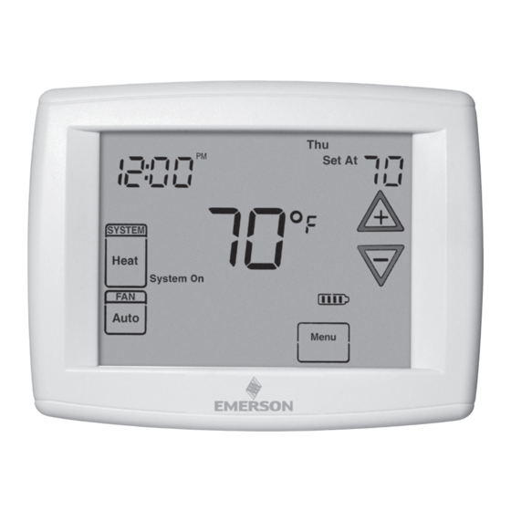
THERMOSTAT QUICK REFERENCE Home Screen Description Figure 8 – Home Screen Display Room Temperature Day of Week Set Temperature Time of Day Note: If is displayed, the Temperature thermostat is battery powered. UP/Down used for System When battery power remaining modifying setpoint Switch is approximately half,... -
Page 5: Installer/Configuration Menu
INSTALLER/CONFIGURATION MENU To enter the menu: Press the Menu touch key. Press and hold for 5 seconds the Installer Config touch key. This displays screen reference #1 in the table below. Screen Reference numbers appear in top right corner of display. Press to advance to the next menu item or to return to a previous menu item. - Page 6 INSTALLER/CONFIGURATION MENU CONFIGURATION MENU Screen Displayed Press Press Option Reference Factory Comments to select from Selected Number (Default) listed options (OFF) dF Selects Dual Fuel feature On or OFF (this item appears if HP1 or HP2 is selected above). (35) dF -5 - 50 Selects Dual Fuel setpoint (°F), dF selected On with outdoor sen-...
- Page 7 INSTALLER/CONFIGURATION MENU Power Stealing Switches ON Power Stealing Switches ON Table 1 (Factory Default) (Factory Default) Backlight Option Backlight Option Backlight Option Backlight Option (Factory Default) (Factory Default) Power Method Momentary Battery Only (before thermostat installation or mV heat systems) No Backlight Momentary Backlight No Backlight Backlight...
- Page 8 INSTALLER/CONFIGURATION MENU "Keypad Lockout and P" = Partial Lockout. Partial When the outdoor temperature falls below the selected Lockout allows only the keys to operate within temperature the gas heat will begin. Default is 35°, but your set temperature limits. can be set in the range of -5 to 50°.
-
Page 9: Operating Your Thermostat
OPERATING YOUR THERMOSTAT Check Thermostat Operation CAUTION NOTE To prevent compressor and/or property damage, if the outdoor temperature is below 50°F, DO NOT operate To prevent static discharge problems, touch side of the cooling system. thermostat to release static build-up before touching any keys. -
Page 10: Automatic Daylight Saving Calculation
OPERATING YOUR THERMOSTAT Manual Operation (Bypassing the Program) override period. The override period can be shortened by Programmable Mode pressing or lengthened by pressing . Program Override period can range from 15 minutes to 7 days. Manual operation will bypass the program and allow you to Example: If you turn up the heat during the morning program, adjust the temperature as you desire. -
Page 11: Automatic Schedule
PROGRAMMING Enter the Cooling Program Cooling Example: 1. In cool, press Auto Schedule once. 1. Press the SYSTEM key until the "Cool" icon appears. 2. Follow Enter Heating Program instructions for entering 2. Press to select a comfortable cooling cooling times and temperatures. temperature (example 75°). - Page 12 PROGRAMMING Worksheet for Re-Programming 5+1+1 and 7 Day Program Heating Wake Up Leave For Work Return Home Go To Bed Program (Morning) (Day) (Evening) (Night) 6:00 AM 70°F Auto 8:00 AM 62°F Auto 5:00 PM 70°F Auto 10:00 PM 62°F Auto 6:00 AM 70°F...
-
Page 13: Troubleshooting
PROGRAMMING Averaging or Weighting Remote Sensors Dual Fuel Temperature Setpoint The thermostat will weight or average the temperature of the When the thermostat is configured for Heat Pump mode indoor remote sensor with the local sensor in the thermostat and the Dual Fuel feature is selected on, the thermostat can for each program period. - Page 14 TROUBLESHOOTING Reset Operation Note: If a voltage spike or static discharge blanks out the display or causes erratic thermostat operation, you can reset the thermostat by removing the thermostat from the wall plate and removing batteries for 2 minutes. After two minutes, replace the batteries and replace thermostat on wall plate.
Need help?
Do you have a question about the OH-1202 and is the answer not in the manual?
Questions and answers