Table of Contents
Advertisement
Optional Accessory: Wall Cover-Up Plate F61-2663, 6 3/4" W x 4 1/2" H
INDEX
Thermostat Installation
2-4
Wiring
2
3-4
Installer Menu
Using the Thermostat
5-7
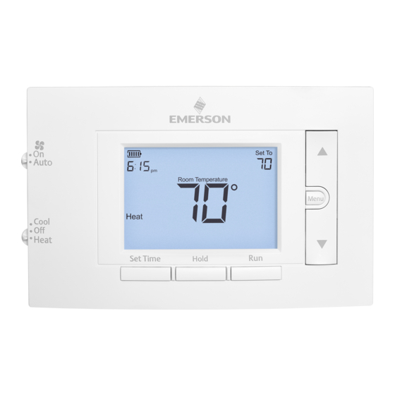
Thermostat Overview
5
User Menu
6
Thermostat Operation
6
7
Thermostat Schedule
Troubleshooting
7-8
Homeowner Help Line
8
SPECIFICATIONS
Electrical Rating:
Battery Power ..................................... mV to 30 VAC, NEC Class II, 50/60 Hz
Input-Hardwire .................................... 20 to 30 VAC, NEC Class II, 50/60 Hz
Terminal Load .......................................... 1.0 A per terminal, 1.5A maximum all terminals combined
Setpoint Range ........................................ 45° to 99° F (7° to 37° C)
Rated Differentials:
Fast
Heat (@ 6°F/ Hr) .................................. 0.5°F
Cool (@ 6°F/ Hr) .................................. 0.9°F
Operating Ambient .................................. 32°F to +105°F (0° to +41°C)
Display Temperature Range ....................... 32°F to +99°F (0 to 37°C)
Operating Humidity ................................. 90% non-condensing max
Shipping Temperature Range ................... -20°F to + 150°F (-29° to +65°C)
Thermostat Dimensions ........................... 3-3/4" H x 6" W x 1-1/8" D
emersonthermostats.com
white-rodgers.com
1F83C-11PR (Programmable)
Installation and Operating Instructions
80 Series Single Stage Thermostat
Battery Powered or Hardwired with Common
Maximum
Thermostat Applications
Stages
Heat/Cool
Conventional Gas, Oil, Electric (mV and
24V), Heat Only, Cool Only or Heat/
Cool Systems
Heat Pump (air source or geothermal)
with no Aux. Heat
MERCURY NOTICE: This product does not contain
mercury. However, this product may replace a product
that contains mercury. Mercury and products containing
mercury must not be discarded in household trash.
Refer to www.thermostat-recycle.org for information
on disposing of products containing mercury.
Med
Slow
0.75°F
1.9°F
1.2°F
1.7°F
PART NO. 37-7478A-EN
WIRING
Refer to equipment manufacturer's instructions for specific system wiring information. After
wiring, see INSTALLER MENU for proper thermostat configuration. Wiring table shown are
for typical systems and describe the thermostat terminal functions.
Terminal Designations
*When both RC and RH wires are present, cut RC/RH jumper (see next page).
**For heat pump systems, add a jumper wire to connect terminals Y and W
1/1
1/1
Precautions
• Do not exceed the specification ratings.
• All wiring must conform to local and national electrical codes and ordinances.
• This control is a precision instrument, and should be handled carefully. Rough handing or
distorting components could cause the control to malfunction.
!
Do not use on circuits exceeding specified voltage.
Higher voltage will damage control and could
cause shock or fire hazard.
Do not short out terminals on gas valve or primary
control to test. Short or incorrect wiring will burn
out thermostat and could cause personal injury
and/or property damage.
1504
THERMOSTAT INSTALLATION
RC*
Power for Cooling
RH*
Power for Heating
Changeover Terminal-Energized in Heat (B) or Cool (O)
O/B
for Heat Pump or Damper Systems
Y**
Cooling Relay
G
Fan Relay
W**
Heating Relay
C
Common wire for 24V (optional with batteries)
WARNING
To prevent electrical shock and/or equipment
damage, disconnect electrical power to system,
at main fuse or circuit breaker box,until
Terminal Function
Leveling Thermostat
Leveling is for appearance only and
will not affect thermostat operation.
CAUTION
!
installation is complete.
2
Advertisement
Table of Contents

Related Manuals for Emerson 1F83C-11PR


Summary of Contents for Emerson 1F83C-11PR
-
Page 1: Specifications
1F83C-11PR (Programmable) THERMOSTAT INSTALLATION Installation and Operating Instructions 80 Series Single Stage Thermostat WIRING Battery Powered or Hardwired with Common Refer to equipment manufacturer’s instructions for specific system wiring information. After wiring, see INSTALLER MENU for proper thermostat configuration. Wiring table shown are for typical systems and describe the thermostat terminal functions. -
Page 2: Test Equipment
INSTALLER MENU (C0ntinued) Installer’s Menu # Default Setting Description Settings (flashing icons) (Hold Menu 8 Seconds) Battery Location Early Start (starts heating or On – start early Premium AA alkaline batteries cooling early so your programmed OFF – start at program are required when C-wire is temperature is reached by the period time... -
Page 3: Thermostat Overview
USER MENU USING THE THERMOSTAT To customize thermostat settings, press the Menu button from the home screen. Use the buttons to highlight Settings and press Next. Use Next and Back to navigate THERMOSTAT OVERVIEW through menu items. Press to change the setting. Before you begin using your thermostat, you should be familiar with its features, display and the location/operation of the thermostat buttons and switches. -
Page 4: Thermostat Schedule
White-Rodgers is a business (Troubleshooting continued on next page) of Emerson Electric Co. The Emerson logo is a trademark and service mark www.white-rodgers.com of Emerson Electric Co. www.emersonclimate.com...
Need help?
Do you have a question about the 1F83C-11PR and is the answer not in the manual?
Questions and answers
I purchased the Emerson 1F83C-11PR. Instructions state that "if both are present, cut jumper wire". What is meant by both?? My heat is gas, and I do have air conditioning. Does this mean I have "both"?? Should I cut the jumper wire or leave it connected as is?
In the instructions for the Emerson 1F83C-11PR, "both" refers to systems that use separate transformers for heating and cooling. For a gas heating system with air conditioning (which typically uses a single transformer), the jumper wire should be left connected.
This answer is automatically generated
How does the cover come off to replace the battery?
To replace the battery on an Emerson 1F83C-11PR thermostat, locate the battery slot on the back of the thermostat. Remove the thermostat from the wall to access the back, then replace the batteries.
This answer is automatically generated
What color wires go to what on the back plate. I have red white yellow blue and green wires. I need to know which color goes to Rc, RH, O/B, Y, G etc. Thank you
For the Emerson 1F83C-11PR thermostat, the wire connections are:
- Red wire: Connect to RC (power for cooling) or RH (power for heating). If both are present, cut the RC/RH jumper.
- White wire: Connect to W (heating relay).
- Yellow wire: Connect to Y (cooling relay).
- Blue wire: Connect to O/B (changeover terminal for heat pump or damper systems).
- Green wire: Connect to G (fan relay).
This answer is automatically generated
Please respond to the second "jumper-wire" question. Thank you.
I truly must say that you need to hold my hand on this question. Regarding my Emerson 1F83C-11PR "jumper wire", separate systems means what? I have a combined gas furnace and cooling system, which operates as a single unit with a single blower. Depending on the season, I switch my existing thermostat from "HEAT" to "COOL". For this new thermostat, do I cut the "jumper wire or leave it connected as is?