Advertisement
Table of Contents
- 1 Installation Instructions
- 2 Applications and Specifi Cations
- 3 Installation
- 4 Equipment Control
- 5 Power System
- 6 Advanced Installer Menu
- 7 USB Upload
- 8 Installation Test
- 9 Check System Operation
- 10 Navigating through Your Thermostat Menus
- 11 Heating Program
- 12 Cooling Program
- 13 Thermostat Settings
- 14 Troubleshooting
- 15 Reset Operation
- Download this manual
Advertisement
Table of Contents

Related Manuals for Emerson Inspire 1HDEZ-1521


Summary of Contents for Emerson Inspire 1HDEZ-1521
-
Page 1: Installation Instructions
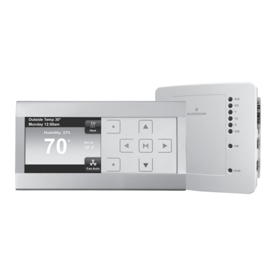
Emerson Inspire ™ 1HDEZ-1521 Installation Instructions Thermostat/Interface Equipment Control... - Page 2 FAILURE TO READ AND FOLLOW ALL INSTRUCTIONS CAREFULLY BEFORE INSTALLING OR OPERATING THIS CONTROL COULD CAUSE PERSONAL INJURY AND/OR PROPERTY DAMAGE. CAUTION To prevent electrical shock and/or equipment damage, disconnect electric power to system at main fuse or circuit breaker box until installation is complete.
-
Page 3: Applications And Specifi Cations
Applications and Specifi cations Confi guration Applications Maximum Options Stages Single Stage Gas, Oil, Electric, Heat Only, Cool Only or Heat Cool Systems Multi Stage Gas, Oil, Electric, Heat Only, Cool Only or Heat Cool Systems Heat Pump Single or Two Compressor Systems with up to 2 Stages of Aux / Em Heat Heat Pump Single or Two Compressor Systems with up... -
Page 4: Installation
Installation Reduce installation time with a USB 1. Go to www.white-rodgers.com 2. Enter 1HDEZ-1521 in the Model Number Search fi eld 3. Select the link for the USB download tool and follow instructions Upload pre-confi gured thermostat settings for every job! -
Page 5: Equipment Control
Installation Equipment Control Mount on wall or exterior surface of HVAC equipment. Control has four mounting holes. Wall anchors and screws are provided for mounting on dry- wall. Drill 3/16" hole for drywall mounting. If mounting on equipment Do Not Mount inside HVAC equipment. Only mount on outside of HVAC equipment. - Page 6 Installation Equipment Control Terminals Operation / Function R ..........24 VAC Transformer RC ..........24 VAC Cooling Transformer* RH ..........24 VAC Heating Transformer* C ..........24 V Transformer Common W/E ..........Heating Stage 1 HP Aux/Em Heat Stage 1 W2 ..........
- Page 7 Installation LED push Wiring to button switch indoor/outdoor equipment Wiring to Sensor R and C from HVAC Wiring to terminal strip or humidification system transformer equipment Status/Fault 7-Segment LED Wiring to DHM2 Wiring to dehumidification Thermostat equipment DHM switch* RJ-11 Connection for HM switch* Configuration Plug-In tool * To use the HVAC transformer to power humidification/dehumidification...
- Page 8 Installation Fig. 1 - Typical Connection of a Single Stage or Multi-Stage System SYSTEM W/E W2 G O/B Single 24 VAC 24 VAC 24 VAC Heat N/A Cool N/A Fan N/A System Stage Power Power for Power Monitor Heating for Cooling 24 VAC Common Multi 24 VAC...
- Page 9 Installation Wiring Guide for Equipment Accessories Fig. 3 - Humidifier. HM terminal provides system 24V on call for humidification HM DRY Non-Powered Humidifier Transformer Fig. 4 - Powered Humidifier. With HM DRY switch in HM2 position, HM and HM2 provide normally open dry contact for low voltage (24V) powered humidifier connection.
- Page 10 Installation Wiring Guide for Equipment Accessories Fig. 6 - System Dehumidification with variable speed blower. For systems where low speed requires connect to normally open 24V powered DHM terminal for low speed connection on air handler/furnace (24V removed on dehumidification call). DHM2 Low Speed DHM2...
- Page 11 Installation Tabs Thermostat 1) Pull the thermostat off the base using tabs shown above. 2) Place base over wire hole in wall and mark mounting hole locations using base as a template. Drill mounting holes. 3) Fasten base snugly to wall using wall anchors and two mounting screws. Leveling is for appearance only and will not affect thermostat operation.
-
Page 12: Power System
Installation Fig. 8 - Thermostat and Equipment Control Wiring LED push Wiring to button switch indoor/outdoor equipment Wiring to Sensor R and C from HVAC Wiring to terminal strip or humidification system transformer equipment Status/Fault 7-Segment LED Wiring to DHM2 Wiring to dehumidification Thermostat... -
Page 13: Advanced Installer Menu
Advanced Installer Menu From the Home screen press the buttons at the same time for three seconds. Press Enter button to save any changes and display the previous menu or press Home to display the Home Screen. Items on the Advanced Installer Menu are: Communicating Devices –... - Page 14 Advanced Installer Menu Communicating Devices This menu item will list each piece of system equipment. Press button to select start Communicating Devices. Press button to select Equipment Control. Press button to select Setup.
- Page 15 Advanced Installer Menu to navigate and press button to select the equipment to be configured. Options for each type of equipment are the following: Indoor GA2 – 2 stage gas furnace GA1 – 1 stage gas furnace EL2 – 2 stage electric heat EL1 –...
- Page 16 Advanced Installer Menu OFF – No humidifier equipment SYS – Humidifier, powered using 24V from system IND – Humidifier, powered using independent 24V source OFF – No dehumidifier equipment SYS – Dehumidifier, powered using 24V from system IND – Dehumidifier, powered using independent 24V source LEDs on the control indicate the thermostat configuration.
-
Page 17: Usb Upload
Installed” for 3 seconds then will display the menu or mode prior to entering the USB upload menu. To use the USB Upload feature, go to www.white-rodgers.com, enter 1HDEZ-1521 in the Model Number Search field and select the USB download link. - Page 18 Advanced Installer Menu Thermostat Summary Indicates the thermostat’s software and version. Heat Pump Lockout (outdoor sensor required) Available only for heat pump systems with indoor electric heat. This feature disables the heat pump and turns on auxiliary heat below the selected outdoor temperature.
- Page 19 Advanced Installer Menu Aux Lockout Temperature (outdoor sensor required) Available for heat pump systems. This setting is the maximum outdoor temperature that is acceptable for auxiliary heat to be used. Heat Cycle Rate Anticipation for heat cycle can be adjusted. Default setting is Medium. If you wish to have longer heat cycles, change to Slow.
-
Page 20: Installation Test
Advanced Installer Menu Installation Test Performs an equipment test to verify proper installation and performance. Only operable on communicating systems with ClimateTalk™. Check System Operation Heating System 1. Press SYSTEM button until Heat is displayed. 2. Press to adjust thermostat setting 1° above room temperature. The heating system should begin to operate and the display will indicate Heat On. -
Page 21: Navigating Through Your Thermostat Menus
Main Menu Navigating through your thermostat menus Your thermostat features a simplified easy to understand menu structure. • Press to enter the Main Menu • Highlight a menu item using the buttons • Enter the item by pressing • Use the and the change menu items and settings •... -
Page 22: Heating Program
Main Menu Time and Day Display When turned on, the current time and day are displayed on the home screen. Outdoor Temp Display When turned on, the outdoor temperature is displayed on the home screen (for use with outdoor sensor only). Humidity Display When turned on, the sensed humidity is displayed on the home screen. -
Page 23: Cooling Program
Main Menu • When you have completed setting all times and temperatures, press Enter to save and display the Heating Program menu. A checkmark appears to indicate the portion of schedule you have programmed Cooling Program After entering Heating Program, press to highlight “Switch to Cool Program”... - Page 24 Main Menu Program – Default is On. Select Off to disable the heating and cooling programs and maintain a constant temperature 24 hours a day. Air Filter Maintenance / Service Reminder / Humidifier Maintenance Default for each is Off. When set to On, a maintenance reminder will appear on the home screen when the system has run for the selected amount of time.
- Page 25 Main Menu Beeper – Default is On. Turns audible prompt on to indicate when a button is pressed. Cycle Humidifier – Default if Off. This feature provides an option that reduces the water usage by up to 50% when a flow-through humidifier is controlled by the thermostat.
- Page 26 Main Menu Comfort or Dehum – Default is Off. Selecting either Comfort or Dehum will automatically reduce indoor humidity with a call for cooling if humidity is 2% above the humidity setpoint. If Comfort is selected, the system will slow the fan speed (variable speed blowers only) to increase the dehumidification process and cool based on the temperature...
- Page 27 Main Menu Temperature Display Adjust – Default is 0°. Your thermostat was accurately calibrated at the factory. However, this option allows you to change the humidity or temperature displayed to match other thermostats in your home. Dehumidification Setpoint – Default is 95%.
-
Page 28: Troubleshooting
Troubleshooting Reset Operation If a voltage spike or static discharge blanks out the display or causes erratic thermostat operation, you can reset the system by performing a power reset. Note: Be sure to record the user’s Main Menu settings. When thermostat is reset, Main Menu and Programming will reset to factory settings. (Installer’s equipment setup options will NOT be affected by the reset.) To reset the programming, clock and configuration settings, press the SYSTEM touch keys simultaneously and hold until the screen resets. - Page 29 Troubleshooting Symptom Possible Cause Correction Action No Cool 1. Cooling system requires service. Heat, Cool or Fan 1. Possible short in Check each wire connection Runs Constantly wiring. to verify they are not shorted 2. Possible short in or touching together. No thermostat.
- Page 30 Troubleshooting Equipment Control Fault Codes Number Displayed in 7 Segment LED Comfort Alert Fault Trip Long Run Time System Pressure Trip Short Cycling Locked Rotor Open Circuit Open Start Circuit Open Run Circuit Welded Contactor Low Voltage System Communication Codes Communication Error For 30 seconds after Communication established, then blank...
- Page 32 PART NO. 37-7343B Replaces 37-7343A 1312 White-Rodgers is a business of Emerson Electric Co. The Emerson logo is a www.white-rodgers.com trademark and service mark www.emersonclimate.com of Emerson Electric Co.
Need help?
Do you have a question about the Inspire 1HDEZ-1521 and is the answer not in the manual?
Questions and answers