Retsch AS 200 Manual
Hide thumbs
Also See for AS 200:
- Operating instructions manual (36 pages) ,
- Operating instructions manual (28 pages)

Related Manuals for Retsch AS 200


Summary of Contents for Retsch AS 200
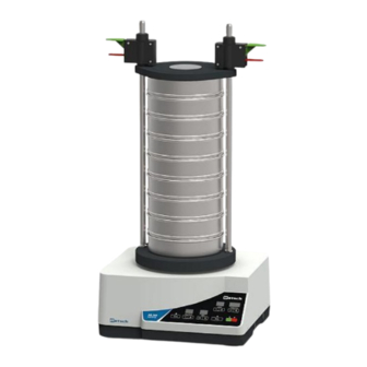
- Page 1 Manual Vibratory Sieve Shaker AS 200 control Translation © Retsch GmbH, 42781 Haan, Retsch-Allee 1-5, Germany | 30.01.2018 Version 0006...
- Page 2 Copyright © Copyright by Retsch GmbH Retsch-Allee 1-5 42781 Haan Germany...
-
Page 3: Table Of Contents
Table of Contents Notes on the Manual ..........................6 Disclaimer ............................6 Copyright............................6 Explanations of the Safety Instructions ..................... 7 General Safety Instructions ....................... 8 Repairs ............................... 9 Confirmation Form for the Managing Operator ................10 Technical Data ............................. 11 Degree of Protection ........................ - Page 4 7.9.3 Save a Programme ........................35 7.10 Signal Tone ............................35 7.11 Operating Hours ..........................35 7.12 Software Version ..........................35 7.13 Date ..............................35 Wet Sieving ............................37 Installing the Slash Protection ......................37 Performing the Wet Sieving ......................38 ®...
- Page 5 Notes on the Manual...
-
Page 6: Notes On The Manual
However, more information thereof can be found in the internet on the webpage of the respective device on the Retsch GmbH homepage (http://www.retsch.com). Revision status: This document revision 0006 refers to the manual "Vibratory Sieve Shaker AS 200 control" in compliance with the Directive of Machinery 2006/42/EC. 1.1 Disclaimer This document has been prepared with due care. -
Page 7: Explanations Of The Safety Instructions
Notes on the Manual 1.3 Explanations of the Safety Instructions In this document the following signs and symbols are being used: Reference to a recommendation and/or an important information Reference to a chapter, table or figure Action instruction │Name│... -
Page 8: General Safety Instructions
All persons concerned with this device in any form. This device is a modern, high performance product from Retsch GmbH and complies with the state of the art. Operational safety is given if the device is handled for the intended purpose and attention is given to this technical documentation. -
Page 9: Repairs
1.5 Repairs This manual does not contain any repair instructions. For safety reasons, repairs may only be carried out by Retsch GmbH or an authorised representative or by qualified service technicians. In case of repair, please inform… …the Retsch GmbH representative in your country, …your supplier, or... -
Page 10: Confirmation Form For The Managing Operator
Confirmation Form for the Managing Operator Confirmation Form for the Managing Operator This manual contains essential instructions for operating and maintaining the device which must be strictly observed. It is essential that they be read by the user and by the qualified staff responsible for the device before the device is commissioned. -
Page 11: Technical Data
Technical Data Technical Data 3.1 Degree of Protection IP54 (IP20 in the area of the sieve carrier passage) 3.2 Emissions CAUTION C4.0011 Possibility of acoustic signals not being heard Loud sieving noises Possible acoustic alarms and voice communication might not be heard. •... -
Page 12: Electromagnetic Compatibility (Emc)
Strong electromagnetic interference fields, such as high-power radio transmitters, can have an adverse influence on the amplitude control of the AS 200 control. Once the source of the interference is eliminated, the AS 200 control will return to normal operation by itself. -
Page 13: Feed Grain Size
230 mm 2 mm 16 mm 125 mm 300 mm The Vibratory Sieve Shaker AS 200 control is designed for the measurement range of 20 µm to 25 mm. 3.9 Payload Maximum sample quantity: 3 kg Maximum sieve stack weight: 6 kg ... -
Page 14: Packaging, Transport And Installation
N5.0014 Complaints Incomplete delivery or transport damage The forwarding agent and Retsch GmbH must be notified immediately in the event of transport damage. It is otherwise possible that subsequent complaints will not be recognised. • Please check the delivery on receipt of the device for its completeness and intactness. -
Page 15: Conditions For The Installation Site
Packaging, Transport and Installation 4.4 Conditions for the Installation Site Installation height: max. 2 000 m above sea level Ambient temperature: 5 °C – 40 °C NOTICE N7.0021 Ambient temperature Temperatures outside the permitted range Electronic and mechanical components may be damaged. ... -
Page 16: Electrical Connection
Packaging, Transport and Installation 4.5 Electrical Connection WARNING W2.0015 Danger to life through electric shock Connection to sockets without protective earth An electric shock can cause burns, cardiac arrhythmia, respiratory arrest, as well as cardiac arrest. • The device may only be operated on sockets with protective earth (PE). -
Page 17: Removing The Transportation Lock
Packaging, Transport and Installation 7 Disposal label 8 Bar code 9 Power version 10 Mains frequency 11 Capacity 12 Amperage 13 Number of fuses 14 Fuse type and fuse strength In the case of queries please provide the device designation (1) or part number (3), as well as the serial number (4) of the device. - Page 18 Packaging, Transport and Installation Fig. 3: Mounting the rubber disc The transportation lock consists of two long hexagonal screws (SM) securing the drive through the sieve plate (ST). Loosen the hexagonal screws (SM) on both sides of the sieve plate (ST) by means of a 13 mm open-end wrench and remove them.
-
Page 19: First Commissioning
Before first commissioning the sieve clamping unit must be installed. The AS 200 control is suitable for test sieves of 100 mm to 203 mm outer diameter. Up to 23 fractions (22 test sieves plus collecting pan with a height of 25 mm), or 11 fractions (10 test sieves plus collecting pan with a height of 50 mm) can be clamped. -
Page 20: Sieve Clamping Unit "Economy" And "Standard
Lay the clamping lid "economy" (C) or "standard" (D) over the threaded rods (A) onto the top test sieve. The top side of the clamping lid "economy" is marked by the Retsch GmbH logo. The clamping lid "standard" is orientated so that the peripheral edge surrounds the test sieves. - Page 21 First Commissioning Place the assembly aid ring (MH1) on the assembly aid (MH2) and slide it down. This presses the O-ring on the quick clamping unit and fixes the clamping lid. Repeat this procedure for the other side. Fig.
- Page 22 There is no need to take off the clamping lid completely from the support rods. NOTICE If the AS 200 control is to be operated with the maximum number of test sieves, longer support rods for the sieve clamping unit "comfort" are necessary. In this case, please contact your local distributor or get in touch with Retsch GmbH directly.
-
Page 23: Operating The Device
The AS 200 control is specially designed for test sieves with an outer diameter from 100 mm to 203 mm. For an optimum measurement result it is recommended to exclusively use test sieves... -
Page 24: Principle Of Operation
6.2 Principle of Operation The AS 200 control performs a vibratory sieving, where the sample material is thrown upwards by the vibrations of the sieve bottom and subsequently falls back down onto the sieve mesh fabric due to gravitation forces. Thereby, the sample material is subjected to a three- dimensional movement, i.e. -
Page 25: Views Of The Instrument
Operating the Device 6.3 Views of the Instrument 6.3.1 Front Fig. 8: Front view of the device with different sieve clamping units... -
Page 26: Back
Operating the Device Element Description Function Threaded rod "economy" and Fixes the sieve stack together with the "standard" clamping lid (C) or (D) and the fixing nut (B) Fixing nut "economy" and Fixes the sieve stack together with the "standard" clamping lid (C) or (D) and the threaded rod Clamping lid "economy"... -
Page 27: Switching On / Off
Data transfer between device and PC 6.4 Switching On / Off Turn on the AS 200 control with the mains switch (I) on the back side of the device. When the device is switched off, it is completely disconnected from the mains. - Page 28 Operating the Device Place the complete sieve stack centrally on the device and clamp the sieve stack ( Chapter "Sieve Clamping Unit "economy" and "standard"" or "Sieve Clamping Unit "comfort""). Set the optimum amplitude value and sieving time ( Chapter "Controlling the Device").
-
Page 29: Controlling The Device
Controlling the Device Controlling the Device 7.1 Operating Controls, Displays and Functions Fig. 10: Operating controls and functions Element Description Function STOP Stops the sieving process. In standby or setting mode, the red LED is lit START Starts the sieving process. During operation, the green LED is lit Pause Interrupts the sieving process. -
Page 30: Stop Process
Controlling the Device 7.3 Stop Process The sieving process will stop automatically after the set process time has elapsed. However, the sieving process can be stopped manually at any time. Press the button (H1) to stop the sieving process. By pressing the button, the sieving process stops, the red LED lights up and the green LED of the... -
Page 31: Amplitudes In Dependence On The Load
7.5.1 Amplitudes in Dependence on the Load The AS 200 control is a resonance sieving machine whose attainable amplitude is depending on the load. In this respect, the mass (sieve stack and sieve clamping unit) fixed to the sieve plate (ST) plays a primary role. -
Page 32: Time
Time setting for continuous operation (left) or with a process time (right) The AS 200 control can be operated either in continuous operation or for a certain time between 1 and 99 minutes. When the device is switched on, the last used setting is displayed. -
Page 33: Interval
With the AS 200 control the amplitude is defined as the total lifting height (SH) of the test sieve. For example, with a set amplitude of 1.2 mm, the test sieve is displaced in the range of -0.6 mm and +0.6 mm around the zero point (= stationary sieve plate (ST)). -
Page 34: Interval Time
99 seconds. The interval time can also be changed during operation by pressing the "+" or "-" button. 7.9 Programme Mode The AS 200 control allows for the saving and recalling of up to 99 parameter sets. The programme settings can only be edited in the setting mode. -
Page 35: Save A Programme
Controlling the Device Set the desired sieving parameters (amplitude, time, interval). The programming can be cancelled by pressing the button. All settings are discarded. 7.9.3 Save a Programme Press the button (H8.2) to save the set sieving parameters in the selected programme memory slot. - Page 36 Controlling the Device A correctly set reminder date is important for the adherence of the calibration intervals. Especially, when the device is used in quality control and thus must be regularly calibrated in accordance with DIN EN ISO 9000 ff.
-
Page 37: Wet Sieving
Wet Sieving Wet Sieving WARNING W6.0001 Danger to life through electric shock Wet sieving An electric shock can cause burns, cardiac arrhythmia, respiratory arrest, as well as cardiac arrest. • Never operate the device in a water drain basin! •... -
Page 38: Performing The Wet Sieving
Wet Sieving Loosen the two upper M4 oval-head screws (LS) on the backside of the AS 200 control. Slide the splash protection from below up behind the top edge of the housing. Retighten the two upper M4 oval-head screws (LS). - Page 39 Wet Sieving Fig. 17: Wet sieving Suspend the sample material in a beaker containing the liquid intended for the wet sieving. To reduce the surface tension and to facilitate the screenings of the material later on, a few drops of surfactant may be added. ...
- Page 40 Wet Sieving Fig. 18: Venting ring If the smallest fraction, that leaves the collecting pan should also be weighted, it must be appropriately collected. After the sieving process, the individual fractions are transferred on suitable tared filters (paper filter) and dried in an oven at 80 °C until the weight remains constant.
-
Page 41: Easysieve
Graphic and tabular presentation of the particle size analysis with EasySieve The software communicates with the scale and the AS 200 control and guides the user through the respective steps. Available parameters, as well as the characteristics to be calculated can be entered in various edit boxes. -
Page 42: Error Messages And Information Notes
Error Messages and Information Notes 10 Error Messages and Information Notes 10.1 Error Messages Error messages inform the user about detected device or programme errors. In the event of an error message, a fault has occurred, in which the operation of the device or the programme is automatically interrupted. - Page 43 Error Messages and Information Notes ® External control by The device is controlled by the EasySieve EasySieve ® software installed on a PC. Close the software to restore the manual control. Display of the software Press the button to exit the display. version...
-
Page 44: Return For Service And Maintenance
When returning a device, attach the return form to the outside of the packaging. In order to eliminate any health risk to the service technicians, Retsch GmbH reserves the right to refuse the acceptance and to return the respective delivery at the expense of the sender. -
Page 45: Cleaning, Wear And Maintenance
Cleaning, Wear and Maintenance 12 Cleaning, Wear and Maintenance 12.1 Cleaning WARNING W8.0003 Danger to life through electric shock Cleaning with water An electric shock can cause burns, cardiac arrhythmia, respiratory arrest, as well as cardiac arrest. • The power cable must be unplugged before cleaning the device. •... -
Page 46: Drying Of Test Sieves
Drying ovens of various sizes can be used for drying test sieves (drying temperature < 80 °C). Additional information concerning ultrasonic cleaning-baths and drying ovens can be found on the Retsch GmbH homepage (http://www.retsch.com). Also ask for the free expert guide Sieve Analysis – Taking a close look at quality. -
Page 47: Replacing The Fuses
If wet sieving is executed, a quarterly examination for tightness of the fluid hoses should be performed. If the AS 200 control is used in quality control, it should be regularly calibrated in accordance with DIN EN ISO 9000 ff. For this purpose please contact your local distributor or get in touch with Retsch GmbH directly. -
Page 48: Accessories
Fig. 21: Test sieves The different versions of the test sieves of Retsch GmbH are supplied in accordance with all current national and international standards: available standards: DIN, ISO, ASTM, BS, NF, CGSB ... -
Page 49: Calibration Service
13.1.2 Calibration Service As a special service Retsch GmbH offers the calibration of the test sieves. All relevant information are recorded during the standard measuring process of the test sieve and confirmed in the required certificate. -
Page 50: Add-On Weight
Accessories 13.3 Add-on Weight If the mass of the sieve stack is too low, the necessary amplitude required for the sieve analysis cannot always be reached. To compensate for this, an additional mass of 2 100 g for test sieves with a diameter ≤ 203 mm can be placed underneath the sieve stack on the sieve plate and be clamped together with the sieve stack. -
Page 51: Disposal
Disposal 14 Disposal In the case of a disposal, the respective statutory requirements must be observed. In the following, information on the disposal of electrical and electronic devices in the European Community are given. Within the European Community the disposal of electrically operated devices is regulated by national provisions that are based on the EU Directive 2012/19/EU on Waste Electrical and Electronic Equipment (WEEE). -
Page 52: Index
Index 15 Index EMC ..............12 Emissions ............11 Accessories ............48 Equivalent continuous sound level ....11 Action instructions ..........7 Error Add-on weight ..........32, 50 E10 ..............42 Ambient temperature .......... 15 E26 ..............42 Amperage ............17 E45 .............. - Page 53 Index green .............. 26 red ..............26 ............... 11 Quick clamping unit ..........26 Lifting the device ..........18 Load diagram ..........31, 40 Location requirements ........12 Range of application of the device ..... 24 Long-term operation ........... 24 Rated power ............
- Page 54 Index Sound level ............11 removing ............17 Sound parameters ..........11 Type plate ............ 16, 27 Spare parts ............48 description ............16 Spray nozzle ............38 Standby mode ............. 27 USB interface ............. 27 START ..............29 Use of the device for the intended purpose ..23 STOP ..............
- Page 60 Copyright © Copyright by Retsch GmbH Retsch-Allee 1-5 42781 Haan Germany...
Need help?
Do you have a question about the AS 200 and is the answer not in the manual?
Questions and answers