
Related Manuals for Retsch SM300


Summary of Contents for Retsch SM300
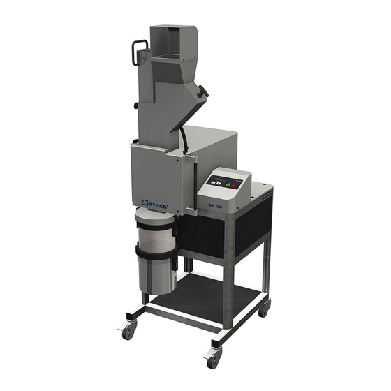
- Page 1 Manual Cutting Mill SM300 Translation © Retsch GmbH, 42781 Haan, Retsch-Allee 1-5, Germany 14.11.2012 0005...
- Page 2 Copyright © Copyright by Retsch GmbH Haan, Retsch-Allee 1-5 D-42781 Haan Federal Republic of Germany...
-
Page 3: Table Of Contents
Notes on the Operating Manual ......................5 Explanations of the safety warnings ....................6 General safety instructions ........................ 7 Repairs ............................... 8 Confirmation ............................9 Transport, scope of delivery, installation ..................10 Packaging ............................10 Transport............................10 Temperature fluctuations and condensed water ................10 Conditions for the place of installation ..................... - Page 4 Mode of Operation of Feed Hopper ....................28 Assembling and using the cyclone ....................29 Cyclone assembly ..........................29 7.1.1 Inserting the wide mouth bottle adapter ..................33 Cleaning and service ........................... 34 Adjusting the cutting bars ........................ 34 Fault messages ............................. 37 Disposal ..............................
-
Page 5: Notes On The Operating Manual
This operating manual does not contain any repair instructions. If faults arise or repairs are necessary, please contact your supplier or get in touch with Retsch GmbH directly. -
Page 6: Explanations Of The Safety Warnings
Notes on the Operating Manual 1.1 Explanations of the safety warnings In this Operating Manual we give you the following safety warnings Serious injury may result from failing to heed these safety warnings. We give you the following warnings and corresponding content. WARNING Type of danger / personal injury Source of danger... -
Page 7: General Safety Instructions
Target group : All persons concerned with the machine in any form This machine is a modern, high performance product from Retsch GmbH and complies with the state of the art. Operational safety is given if the machine is handled for the intended purpose and attention is given to this technical documentation. -
Page 8: Repairs
Reperatur en 1.3 Repairs This operating manual does not contain any repair instructions. For your own safety, repairs may only be carried out by Retsch GmbH or an authorized representative or by Retsch service engineers. In that case please inform:... -
Page 9: Confirmation
Confirmation Bes tätigung 2 Confirmation This operating manual contains essential instructions for operating and maintaining the device which must be strictly observed. It is essential that they be read by the operator and by the qualified staff responsible for the device before the device is commissioned. -
Page 10: Transport, Scope Of Delivery, Installation
Transport, scope of delivery, installation 3 Transport, scope of delivery, installation 3.1 Packaging The packaging has been adapted to the mode of transport. It complies with the generally applicable packaging guidelines. NOTICE Storage of packaging – In the event of a complaint or return, your warranty claims may be endangered if the packaging is inadequate or the machine has not been secured correctly. -
Page 11: Removing Transport Safeguards
Transport, scope of delivery, installation NOTICE Atmospheric humidity – Electronic and mechanical components may be damaged and the performance data alter to an unknown extent. • Do not exceed the admissible range for atmospheric humidity. 3.5 Removing Transport Safeguards Fig. 1: Removing Transport Aid Lift the device only by the transport aid (TH). -
Page 12: Mounting The Feed Hopper
Transport, scope of delivery, installation Fig. 2: Removing the Transport Safeguard • Remove the transport aid (TH). • Unlock the grinding chamber door by pulling the mini detent pin (E) upwards and pressing the handle of the door latch (F) backwards. •... -
Page 13: Installation Of The Machine
Transport, scope of delivery, installation • Push the plunger downwards. • Screw the two provided socket-head screws (S) through the hinge on the feed hopper into the enclosure. • At first, tighten the screws only slightly. • Close the grinding chamber door. •... -
Page 14: Electrical Connection
Transport, scope of delivery, installation NOTICE Installation of the machine – It must be possible to disconnet the machine from the mains at any time. • Install the machine such that the connection for the mains cable is easily accessible. 3.8 Electrical connection WARNING When connecting the power cable to the mains supply, use an external fusethat... - Page 15 Transport, scope of delivery, installation CE marking Disposal label Bar code Power version Mains frequency Capacity Amperage Number of fuses Fuse type and fuse strength In the case of questions please provide the device designation (1) or the part number (3) and the serial number (4) of the device.
-
Page 16: Technical Data
Technical data 4 Technical data 4.1 Use of the machine for the intended purpose Target group: Users, managing operators (owners) Machine type designation: SM 300 The heavy-duty SM 300 cutting mill serves to grind flexible, hard-ductile and fibrous products and product mixtures in batches or continuously. The SM 300 is not designed for grinding wet or moist materials. -
Page 17: Emissions
Technical data NOTICE Area of use of the machine – This machine is a laboratory machine designed for 8-hour single-shift operation. • This machine may not be used as a production machine nor is it intended for continuous operation. 4.2 Emissions CAUTION Damage to hearing The level of noise can be high depending on the type of material,... -
Page 18: Required Floor Space
Technical data 4.8 Required floor space 1090 mm x 765 mm - no safety spacing needed... -
Page 19: Operating The Machine
Operating the machine 5 Operating the machine 5.1 Views of the Instrument Fig. 6: Front view... - Page 20 Operating the machine Fig. 7: Front view from the left (detail) Fig. 8: Rear view...
-
Page 21: Operating Elements And Displays
Operating the machine Fig. 9: View of grinding chamber 5.2 Operating elements and displays Fig. 10: View of the control panel and the display... -
Page 22: Overview Table Of The Parts Of The Device
Operating the machine 5.3 Overview table of the parts of the device Element Description Function Safety guard for the feed hopper Prevents contact with the feed hopper Plunger Releases the material feed chute in pulled state. Pushes grinding material onto the rotor. Metering plunger Pushes the grinding material into the feed chute area of the fill plunger... -
Page 23: Opening And Closing Of The Grinding Chamber
Operating the machine 5.4 Opening and closing of the grinding chamber The motor must come to a complete stop before the mill housing can be opened. Stop the device by pressing the STOP button (G6). Pull the mini detent pin (E) upwards. ... -
Page 24: Replacing The Rotor
Operating the machine Fig. 12: Inserting the bottom sieve 5.6 Replacing the rotor CAUTION Injuries in the form of cuts Sharp cutting edges on the rotors and cutting bars – The sharp cutting edges on the rotors and cutting bars can injure hands. •... - Page 25 Operating the machine • Pull the rotor (H) approx. 10 mm out of the grinding area until it can be freely rotated. Fig. 2: Freely rotate the rotor Fig. 3: Checking the cutting gap • Using a feeler gauge (BL), check the cutting gap of all three cutting bars (SL).
-
Page 26: Removing The Rotor
Operating the machine 5.6.1 Removing the Rotor • Stop the device. • Open the grinding area door. • Screw the removal grip (EG) onto the rotor and pull the rotor from the drive shaft. Fig 5: Removal grip 5.6.2 Inserting the Rotor •... -
Page 27: Starting The Grinding Process
Operating the machine • Insert the bayonet fixing(BV) on the ring sieve (J) into the discharge flange(AF), as shown in the illustration. • Turn the ring sieve in a clockwise direction so that the bayonet fixing will engage. • To remove the ring sieve, pull out the latching bolt (RB) to release the bayonet fixing (BV). -
Page 28: Mode Of Operation Of Feed Hopper
Mode of Operation of Feed Hopper 6 Mode of Operation of Feed Hopper NOTE Motor blockage The material being ground clogs the rotor – Blockages can damage mechanical components. • Feed material only while the device is running. • Dose the material feed to suit the properties of the material. •... -
Page 29: Assembling And Using The Cyclone
Assembling and using the cyclone 7 Assembling and using the cyclone 7.1 Cyclone assembly CAUTION 3.V0014 Injuries to limbs Rotating blade – Can cause injury to hands and feet. • Keep hands and feet away from the device openings when the device is switched on. •... - Page 30 Assembling and using the cyclone Fig. 17: Fastening the discharge flange • Insert the retrofit dust removal (U). • Tighten the screw (U1). Fig. 18: Inserting the plug for the sliding block • Insert the plug (HS) into the back (flat surface) of the sliding block (NS). Fig.
- Page 31 Assembling and using the cyclone Fig. 20: Turning the sliding block • Push in the sliding block against the resistance of the plug and turn the sliding block to the position indicated. • Insert the second sliding block in the same way. Fig.
- Page 32 Assembling and using the cyclone • Turn the side tube to the discharge flange and push the coupling (Z1) onto the adapters on the discharge flange. Fig. 23: Assembled cyclone CAUTION Before using the industrial vacuum cleaning, read the operating instructions supplied with the vacuum cleaner.
-
Page 33: Inserting The Wide Mouth Bottle Adapter
Assembling and using the cyclone 7.1.1 Inserting the wide mouth bottle adapter Fig. 25: Inserting the wide mouth bottle adapter • Insert the adapter for wide mouth bottles (Z5) into the outlet opening of the cyclone (AZ) . • Affix the adapter using the threaded pin (GS). •... -
Page 34: Cleaning And Service
Cleaning and service 8 Cleaning and service 8.1 Adjusting the cutting bars The cutting gap must be checked to ensure that the device is functioning satisfactorily (target distance 0.3mm). For this reason the cutting bars (SL) are arranged so that they can be shifted to permit adjustments to the cutting gap. Fig. - Page 35 Cleaning and service Fig. 7: Freely rotate the rotor Mind. 0,3mm Fig. 8: Adjusting the cutting gaps • Using a feeler gauge (BL) check the cutting gap for all three cutting bars (SL). It should be at least 0.3 mm. The feeler gauge (BL) must be placed on both cut areas as shown in the diagram.
- Page 36 Cleaning and service • By twisting the stud bolts (U) to the right, slide the cutting bar closer to the rotor blade and thereby reduce the cutting gap. Increase the cutting gap by twisting to the left. • Tighten the screw (WS) and check the cutting gap. Repeat the process if necessary.
-
Page 37: Fault Messages
Fault messages 9 Fault messages F.01 Overload Frequency converter switched off because of overloading F.04 Open the door Close the door and close the lock. F.04.- Open the lock Close the lock F.11 Engine is overheated. Starting impossible. Please wait until it cools down. F.15 Fault in the safety circuit of the Door switch opened,... -
Page 38: Disposal
Disposal 10 Disposal Please observe the respective statutory requirements with respect to disposal. Information on disposal of electrical and electronic machines in the European Community. Within the European Community the disposal of electrically operated devices is regulated by national provisions that are based on the EU Directive 2002/96/EC on Waste Electrical and Electronic Equipment (WEEE). -
Page 39: Index
11 Index Access to the cutting bars........34 Electrical connection .......... 14 Adjusting the cutting bars ........34 Emissions ............17 Adjusting the cutting gaps ng ......35 Explanations of the safety warnings ....6 air exit ..............27 External fuse ............14 air flow.............. - Page 40 Installing the cyclone .......... 31 Removal grip ............26 IP20 ..............17 Removing the discharge flange ......29 Removing the Rotor ........... 26 Removing the Transport Safeguard ..... 11, 12 Mains frequency ..........15 Removing transport aid ........11 Manufacturer’s address ........14 Removing Transport Safeguards .......
- Page 41 Authorized person for the compilation of technical documents: J. Bunke (technical documentation) The following records are held by Retsch GmbH in the form of Technical Documentation: Detailed records of engineering development, construction plans, study (analysis) of the measures required for conformity assurance, analysis of the residual risks involved and operating instructions in due form according to the approved regulations for preparation of user information data.
- Page 44 Copyright ® Copyright by Retsch GmbH Haan, Retsch-Allee 1-5 D-42781 Haan Federal Republic of Germany...
Need help?
Do you have a question about the SM300 and is the answer not in the manual?
Questions and answers