
Related Manuals for Metertech SP-8001


Summary of Contents for Metertech SP-8001
- Page 1 Provide Accurate Results Operational Manual UV/Visible Spectrophotometer SP-8001 Metertech Inc. Version 1.2...
- Page 2 Metertech Inc. provides this publication “as is” without warranty of any kind, either express or implied, including, but not limited to the implied warranties of merchantability or fitness for a particular purpose. All rights are reserved, including those to reproduce this publication or parts thereof in any form without permission in writing from Metertech Inc.
-
Page 3: Table Of Contents
Metertech Inc. Contents Chapter 1 Introduction -------------------- §1-1 Specification -------------------- §1-2 Safety Notes -------------------- Chapter 2 Installation -------------------- §2-1 Unpacking -------------------- §2-2 Installation -------------------- Chapter 3 General -------------------- §3-1 User Interface -------------------- §3-2 General Function Description -------------------- §3-3 Initialization --------------------... - Page 4 Metertech Inc.
-
Page 5: Chapter 1 Introduction
In order to obtain maximum performance and trouble-free operation with the SP-8001, It is recommended that you carefully read this manual before using the SP-8001, and thereafter keep it close at hand for future reference. -
Page 6: Safety Notes
Metertech Inc. § 1-2 Safety Notes Although this SP-8001 UV-VIS Spectrophotometer is user friendly, the instrument and its accessories described in this manual are designed to be used by properly trained persons only. READ THIS SECTION CAREFULLY BEFORE INSTALLING AND USING THE INSTRUMENT AND ITS ACCESSORIES. -
Page 7: Chapter 2 Installation
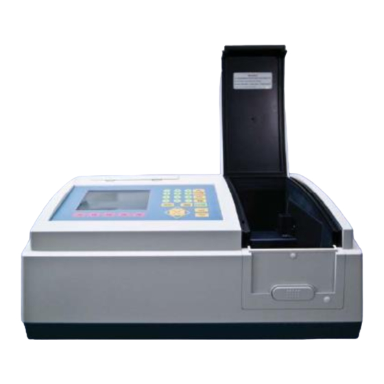
§ 2-1 Unpacking The SP-8001 (Figure 2.1 and Figure 2.2) should be delivered with intact packaging that contains one carton with items listed in the packing list. Unpack the carton and inspect carefully. -
Page 8: Installation
◆ near centrifuge Check and set the voltage. The SP-8001 can be performed with selective power supply at 110 or 220 Vac 50/60Hz from a properly wired and grounded single phase power outlet. Check the voltage shown at 110/220V slide above power receptacle on rear panel. If it is not the desired, use flat screw driver to move the slide left or right to obtain the correct voltage. -
Page 9: Chapter 3 General
Metertech Inc. Chapter 3 General The SP-8001 is designed to be a self-contained instrument and can work as a standalone machine or can work with other peripherals together. The SP-8001 has one membrane-type keyboard and a 320X240 LCD display as the user interface. - Page 10 Metertech Inc. stored in memory. In this file list, users can view all parameter settings in different operation modes that is distinguished by the first 2 letters in the first column. For example, PH represents for “Photometric” mode. Filenames are shown in the second column, while the corresponding time in the third column.
-
Page 11: General Function Description
Metertech Inc. § 3-2 General Function Description Functions being used in the SP-8001 are listed in the corresponding modes and are shown in structured maps. For those functions being widely used in most of the modes will be described below. - Page 12 Metertech Inc. 12:00:00 500.0nm 0.000A >>> File Name:ART Press UP DOWN key to select... Figure 3.4 Filename input screen Next Screen Accept the current settings and switch into the measuring display screen. Once get the sample(s) ready, press READ for proceeding the measurement according to the setup.
-
Page 13: Initialization
Metertech Inc. § 3-3 Initialization Turn on the power of the SP-8001, a start-up screen (Figure 3.5) shows up and the initialization of system will be automatically done. The version of software coming up with the instrument is also shown in the start-up screen. - Page 14 Metertech Inc. same as described before by using the QUICKRUN key. Sample Control will be functioning only when the multi-cell holder or the sipper is used.
-
Page 15: Chapter 4 System Setup
Metertech Inc. Chapter 4 System setup In System Main Menu, selecting item 6 will get into the System Setup Menu screen (Figure 4.1). In this screen, users are allowed to alter several parameters described below. In this screen only one function, Load B-Line, is available. - Page 16 Metertech Inc. Second as necessary. Setup Lamp Use function keys to set up parameters for visible and UV lamps (Figure 4.3). Switch UV is for switching ON/OFF of UV lamp. Reset Vis Hr is for resetting the usage time of the tungsten lamp.
- Page 17 Metertech Inc. 12:00:00 500.0nm 0.000A Serial Port Parameter Setup 1.Baud rate :38400 2.Bit length 3.Parity check :NONE 4.Stop bit 5.Remote status :OFF Press < > key to select... Print Prev Data Screen Figure 4.5 Serial Port Parameter Setup screen Setup RS-232 Parameters for RS-232 can be set up through instructions shown in the screen (Figure 4.5).
- Page 18 Metertech Inc. Setup Hardware In this option, three adjustable items are shown (Figure 4.6). arrow keys to move cursor to proper position and proceed as instructed at the bottom of this screen. UV/VIS Change Wavelength allows users to set switching point for UV/VIS lamps, while 363nm is set as default.
- Page 19 Metertech Inc. 12:00:00 BANDWIDTH 676.0nm 100. 50.0 676 nm 1=655.59nm =657.44nm Bandwidth=1.85nm max=656.12nm Measurement completed... Print Prev Data Screen Figure 4.7 Bandwidth measurement screen Measure Base line To execute the base-line measurement immediately after the ENTER key is pressed. Search Zero Position...
-
Page 20: Chapter 5 Photometric
Metertech Inc. Chapter 5 Photometric This is a simple measurement mode with fixed wavelengths. According to the parameter setup, users can repeat a measurement and a table of the measurement results will be shown. The results can be printed with proper settings. -
Page 21: Photometric Function Structure
For functions not described below, please refer to General function description section. § 5-3 Basic Photometric Measurement The following is a description of the basic procedure for carrying out measurement in the SP-8001 Photometric measurement mode. For example, five samples are ready to proceed photometric measurement in 4 wavelengths: 400, 450, 500, and 550. - Page 22 Metertech Inc. to the proper position. When all is done, press F5 Next Screen to next step. Step 3. Get a sample ready and press READ. The reading of that sample will be displayed on the screen. Repeat this step for other four samples.
- Page 23 Metertech Inc. and press ENTER. The reading of the measurement will show up in the screen. Step 3. After the measurement, press F3 Mode A/C/%T can switch reading into different formats: A as for Abs, C as for concentration, and %T as for transmittance.
- Page 24 Metertech Inc. Step 6. After data saved, pressing F1 View Data can get into the Data File List screen (Figure 5.8). will show the first 15 sets of data being saved. In this screen, functions F1 Prev Page is for viewing 12:00:00 LAMBDA 500.0nm...
-
Page 25: Chapter 6 Spectrum
Metertech Inc. Chapter 6 Spectrum This is the mode in which spectral measurement is performed. Measured spectra can be saved to memory and be subjected to various data manipulation described in details below. The measured spectra can be zoomed by changing the interested range. -
Page 26: Spectrum Function Structure
Metertech Inc. Measure Mode Selecting measurement results in ABS as for absorbance or in %T as for transmittance. Low Value For entering the lower limit of measurement result between –0.3 and 2.99 for ABS and between 0 and 119.9 for %T, respectively. -
Page 27: Basic Spectrum Measurement
To redraw the graph from data obtained in the current measurement. § 6-3 Basic Spectrum Measurement The following is a description of the basic procedure for carrying out measurement in the SP-8001 Spectrum measurement mode. For example, a spectrum of sample is to be measured from 400nm to 800nm and the results should be bounded between 0 and 1.5Abs. - Page 28 Metertech Inc. 12:00:00 SPECTRUM 500.0nm Parameter Setup 1.Start wavelength(nm) :400.0 2.Stop wavelength(nm) :800.0 3.Measure mode :ABS 4.Low value(ABS) :0.00 5.High value(ABS) :1.50 6.Scan speed(nm/min) :1000 7.Overlay screen :Yes Number from 190 to 1098... Load Save Print Sample Next Param Param...
- Page 29 Metertech Inc. 12:00:00 SPECTRUM 800.0nm 1.50 0.75 0.00 400 nm Press READ when ready... Smooth Zoom Show Peak Origi- Data Data Track Valley Figure 6.4 Functions for manipulating graph Step 6. If users want to view part of the graph, function Zoom Data is designed for this purpose.
- Page 30 Metertech Inc. 12:00:00 SPECTRUM 533.2nm 1.50 0.75 0.00 400 nm Press < > key to move... View Save Print Data Data Data Figure 6.6 Graph under Show Track function During the tracing process, corresponding values for traced point will be displayed at the up right corner in the screen.
- Page 31 Metertech Inc. 12:00:00 SPECTRUM 800.0nm 1.50 0.75 0.00 400 nm Press hot key to processing... View Search Search Less More Data Peak Valley Point Point Figure 6.8 Searching peaks of the spectrum viewed by pressing F1 View Data to see the wavelength and the corresponding reading (Figure 6.9).
-
Page 32: Chapter 7 Timescan
Metertech Inc. Chapter 7 Timescan This is the mode in which absorbance versus time measurement of a sample is performed for the accurate study of continuous changes in reaction rates. Delay Time can be set before the start of Scan Time. -
Page 33: Timescan Function Structure
Metertech Inc. Low Value For entering the lower limit of measurement result between –0.3 and 2.99 for ABS and between 0 and 119.9 for %T, respectively. High Value For entering the upper limit of measurement result between –0.29 and 3.00 for ABS and between 0.1 and 120.0 for %T, respectively. -
Page 34: Basic Timescan Measurement
To redraw the graph from data obtained in the current measurement. § 7-3 Basic TimeScan Measurement The following is a description of the basic procedure for carrying out measurement in the SP-8001 TimeScan measurement mode. For example, users want to know the measurement change of a sample in a time span of 300 seconds at wavelength 500nm. - Page 35 Metertech Inc. Step 4. After the measurement, functions can be selected in the same way as in Spectrum mode. 12:00:00 TIMESCAN 500.0nm 101. 100. 99.0 0 sec Press READ when ready... Access Mani- Clear Prev Data pulate Graph Screen Figure 7.3 Measurement in TimeScan screen...
-
Page 36: Chapter 8 Kinetic
Metertech Inc. Chapter 8 Kinetic In this mode, the time-dependent changes in absorbance (ABS) at a fixed wavelength are measured and recorded. A typical application in this mode is the measurement of an enzyme activity. The time changes in absorbance will be displayed on screen and the absorbance can be found at each sampling interval, set according to Lag Time plus with Rate Time. -
Page 37: Kinetic Parameter Setup
Metertech Inc. § 8-1 Kinetic Parameter Setup Wavelength (nm) For entering the value of wavelength to be used in the Kinetic mode. The value should range from 190 to 1100. Sampling number For entering the sampling number of a measurement in the Kinetic mode. -
Page 38: Kinetic Function Structure
Metertech Inc. § 8-2 Kinetic Function Structure Kinetic Load Param Save Param Change Scale Print Data Repeat Measure Sample Control Print Data Data List Next Screen Sample Control Prev Screen Linear Fit Manipulate Clear Graph Show Track Print Data Print Data... -
Page 39: Basic Kinetic Measurement
§ 8-3 Basic Kinetic Measurement The following is a description of the basic procedure for carrying out measurement in the SP-8001 Kinetic measurement mode. For example, users want to know the reaction of a reagent in a time span of 60 seconds after 60-second lag time by sampling 5 times at wavelength 405nm, assuming that factor is 3253 and unit is set as U/L. - Page 40 Metertech Inc. 12:00:00 KINETIC 405.0nm 0.540A 1.00 0.35 -0.3 T=60.0 Factor=3253.000 ABS/T=0.11308( ABS/min) C /T=367.86414( U/L/min) =0.00188T + 0.27194 Press READ when ready… Data Mani- Clear Print Prev List pulate Graph Data Screen Figure 8.3 Kinetic measuring screen 12:00:00 KINETIC 405.0nm 0.540A...
-
Page 41: Chapter 9 Quantitative
Metertech Inc. Chapter 9 Quantitative This is the mode in which the concentration of an unknown sample under a specific wavelength can be determined by creating a calibration curve from standard samples. Four methods for curve fitting can be selected: straight line with or without passing through origin and 2 order polynomial with or without passing through origin. -
Page 42: Quantitative Function Structure
Metertech Inc. Have Unit (Yes/No) Selecting the unit option for measurement results. When Yes is selected, pick the right unit out of the thirteen build-in units in table. Method Four methods of data fitting are available: 1’ord.(Origin) for straight line through origin, 1’ord.(No Org) for straight line not passing through origin, 2’ord.(Origin) for 2... -
Page 43: Basic Quantitative Measurement
Metertech Inc. § 9-3 Basic Quantitative Measurement The following is a description of the basic procedure for carrying out measurement in the SP-8001 Quantitative measurement mode. In this mode, users use standard samples to determine unknown samples. For example, there are three standard samples with known concentration and absorbance. - Page 44 F1 View Equati will allow users to view details of the fitted curve and it is described in step 6. Step 5. In the Quantitative Measure Sample screen (Figure 9.5), get the unknown sample ready and press READ, then the SP-8001 will measure the absorbance of the sample and calculate the 12:00:00 QUANTITATIVE 500.0nm...
- Page 45 Metertech Inc. 12:00:00 QUANTITATIVE 500.0nm Measure Sample -------------------------------------- Sample No. Conc.( G/L) 0.521 5.2100 1.137 11.370 2.325 23.250 Press READ when ready... Print Sample Prev Data Control Screen Figure 9.5 Quantitative Measure Sample screen 12:00:00 QUANTITATIVE 500.0nm Linear Fitting -------------------------------------- Conc.
-
Page 46: Chapter 10 Accessories
Metertech Inc. Chapter 10 Accessories Metertech. Inc. designed several optional accessories to meet users’ specific purposes while the Single cell holder is a standard accessory. When an optional accessory is to be used, users should turn off the instrument first and then do the hardware installation as well as the cable connection. - Page 47 Metertech Inc. Cell number that is in the measurement position. A Multi-Cell Parameter Setup screen (Figure 10.2) will show up when function Sample Control being pressed. Detailed settings and respective functions will be described below. 12:00:00 500.0nm 0.000A Multi-Cell Parameter Setup 1.Driver cell Number(1-6)
-
Page 48: Sipper
Metertech Inc. § 10-2 Sipper The Sipper (Figure 10.3) is an optional accessory that enables samples to be drawn into a flow cell for automatic measurement. After the measurement is complete the sample may be sent to a waste bottle or returned to its original vessel. - Page 49 Metertech Inc. applies on the sipping operation for Sipper Time. Pre Air Purge Time (sec) For entering the value of time during which Sipper will do the air purge operation for the previous sample. The value should range from 0 to 99.9.
-
Page 50: Chapter 11 Maintenance
Metertech Inc. Chapter 11 Maintenance The information given in this section deals only with those parts of maintenance or service which can be safely carried out by users. Work other than those detailed later should be carried out by a trained service engineer. -
Page 51: Replacement Of Lamps
Metertech Inc. § 11-2 Replacement of Lamps This instrument is designed for easy access in lamp replacement. Minimum adjustment is required for the replacement. The tungsten halogen lamp is seated in a specially designed holder that is located in the right half part in the lamp compartment (Figure 11.1). - Page 52 Metertech Inc. deuterium lamp. Pull the deuterium lamp straightly upward to remove. Put a new deuterium lamp back to the holder and screw it tightly. ◆ ◆ Reconnect the rapid connector of the deuterium lamp. Remount the cover of lamp compartment.
-
Page 53: Appendix A Thermal Controller Operation
Metertech Inc. Appendix A Thermal controller operation § A-1. Installation of thermal controller on SP8001 machine -Power off SP8001 machine. -The thermal controller can be applied to SP8001 in two approaches. It can be an independent unit for rectangular cuvette, or accompanied with sipper for flow through cell. - Page 54 Metertech Inc. § A-3. Important notes -The thermal controller is designed to adapt for two types of flow cell; aperture height with 8.5 mm and 15 mm. The default height is 8.5 mm. If 15 mm height is needed, please remove an aluminum block right down the bottom surface of cell holder with a cross type screw driver.
-
Page 55: Appendix B Sipper Operation Instruction
Metertech Inc. Appendix B Sipper operation § B-1. Installation of sipper on SP8001 machine -Power off SP8001 machine. -Remove the front panel of cell compartment of SP8001 by loosing two M3 screws behind it. -A sipper assembly as shown on fig. 1 includes one pumping drive, one pinch... - Page 56 Metertech Inc. -There are six parameters to be set for the sipper to be properly operated. #1 is pump speed selection for sampling solution at low , medium or high speed. #2 and #4 are for air purge times setting, the pump is always preset at high speed. If you...
- Page 57 Metertech Inc. flow cell& tubes peristaltic tube pinch valve button stop 9-pin(small) connector screw hole sample inlet 24-pin(large) connector sample outlet pumping wheel thermal water inlet&outlet Figure 1. Sipper Assembly(with flow cell connected)
-
Page 58: Appendix C Setting Of Usb Serial Port
Metertech Inc. Appendix C Setting of usb serial port If your Windows(XP/98SE) PC has USB ports only, please install the attached USB to RS232 driver on PC. Connecting the USB to RS232 cable between PC and the machine, then power it up. Please set up your Windows(XP) computer as follow. - Page 59 Metertech Inc. (Figure C-2) (Figure C-3)
- Page 60 Metertech Inc. (Figure C-4)
Need help?
Do you have a question about the SP-8001 and is the answer not in the manual?
Questions and answers