Table of Contents
Advertisement
Quick Links
Advertisement
Table of Contents

Related Manuals for Metertech 6+


Summary of Contents for Metertech 6+
- Page 1 Operational Manual Miniphotometer Model 6+ PN 475101...
- Page 2 Product Warranty Your Eurofins Abraxis Model 6+ Miniphotometer is guaranteed to be free of defects in workmanship and materials under normal use for a period of one year from the date of purchase by the customer. The liability of Eurofins Abraxis is limited to repair or replacement and in no event shall Eurofins Abraxis be liable for any collateral or consequential damages ot loss.
-
Page 3: Table Of Contents
Contents Section 1 Installation -------------------------------------------------------------------------------- 1 1-1 Unpacking ------------------------------------------------------------------------------------- 1 1-2 Standard Equipment --------------------------------------------------------------------- 1 1-3 Whole Unit ---------------------------------------------------------------------------------- 1 -------------------- 1-4 Installation Section 2 General system information -------------------- -------------------- 2-1 General Introduction 2-2 Specifications -------------------- Section 3 Function description -------------------- -------------------- 3-1 Modes... -
Page 4: Section 1 Installation
Section 1 Installation Unpacking The packing contains the items stated below. Unpack the carton and inspect carefully. If any part is damaged or missing, contact your dealer immediately. Save the packing materials in case the unit may need to be repacked or returned for service. Standard Equipment Q’ty DESCRIPTION... -
Page 5: Installation
Connect with your PC or printer if desired. LCD of the unit will display the greeting message “Metertech,Miniphotometer” and then “SYSTEM MENU, .. 1:ABS MODE” Refer details of operation in Section 4. -
Page 6: Section 2 General System Information
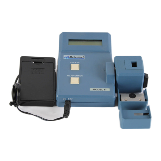
Section 2 General system information 2-1 General Introduction The Convertible Well-strip/Cuvette Reader Model 6 is a portable miniphotometer designed to do ELISA testings in either 1x8/1x12 microwell strips or round/square cuvettes by interference filter for wavelength of 400-700nm. Model 6 is a user-friendly ELISA reader. - Page 7 Output DC 12V/700mA Sample Compartment Strip : 9x13mm standard well-strip Cuvette: Round 12mm in diameter Dimension Whole unit: 150mm(W) 170mm(D) 50mm(H) 50mm(W) Optical unit: 50mm(D) 50mm(H) Weight 850 grams (with power adapter) Options 10mm square cuvette holder Centronic cable RS-232 cable Thermal printer (40 column)
-
Page 8: Section 3 Function Description
Section 3 Function description Model 6 uses a low voltage Tungsten lamp for sample illumination. Lamp life is conserved by being only turned on for the brief measurement period after a button is pressed to blank or read a sample. Light from the lamp is collected by the condenser lens set and focalized to a narrow beam in the sample well/cuvette below. -
Page 9: 3-2-1Well-Strip Holder
3-2-1 Well-strip Holder The supplied standard well-strip holder can fit 9x13mm well-strip (1x8 or 1x12). Turn the optical unit in position as fig 3-1 (Note: figures of filter in right reading way) to install/remove the holder. 3-2-2 Cuvette Holder Remove well-strip holder, and turn counterclockwise for 90 degrees to install cuvette holder as Fig 3-2. -
Page 10: Control Button Instruction
Control Button Instruction Model 6 is fully operated only with two touch buttons. READ/ENTER button controls - to enter the selected mode to read Blank, Standard, and Sample - to move cursor when keying in Factor and Standard Concentration values SEL/ESC button controls - to select different mode - to return to SYSTEM MENU, previous action... -
Page 11: Section 4 Operation
Section Operation Power is supplies to the unit from an adaptor or from any 12VDC battery bag. After power is turned on, LCD displays the greeting message “Meteretch, Miniphotometer” and followed by “SYSTEM MENU, 1:ABS MODE”. Then you may proceed your required mode in either well-strip or cuvette as procedures stated below. -
Page 12: Concentration Mode(Without Standard)
Concentration Mode (with no standard) Press SEL/ESC button from “SYSTEM MENU, 1:ABS MODE”. LCD displays “SYSTEM MENU, 2:A-CONC MODE(1)”. Press READ/ENTER button. LCD displays “KEY IN FACTOR, FACTOR=0000.0”. Key in Factor value (0000.0-9999.9) as instructed in Section 3-3-**. LCD displays “A-CONC MODE(1), READ BLANK”. Insert the blank well or place the blank cuvette into the read position. -
Page 13: Concentration Mode(With Standard)
4-3 Concentration Mode (with standard) Press SEL/ESC button twice from display “SYSTEM MENU, 1:ABS MODE”. LCD displays “SYSTEM MENU, 3:A-CONC MODE(2)”. Press READ/ENTER button, LCD displays “KEY IN CONCEN, CONCEN=00000.00C”. Key in Concentration value(00000.00-99999.99) of standard as instructed in Section 3-3-**. LCD displays “A-CONC MODE(2), READ BLANK”. -
Page 14: Cut Off Mode
4-4 Cut Off Mode Press SEL/ESC button three times from display “SYSTEM MENU,1:ABS MODE”. LCD displays “SYSTEM MENU,4:CUT OFF MODE”. Press READ/ENTER button, LCD displays “KEY IN COEFF A, A=0.000”. Key in positive control coefficient A(0.000-9.999) of standard as instructed in Section 3-3- **.Please read note 1 below for the formula of cut off value(COV). -
Page 15: Print Function
4-5 Print Function Press SEL/ESC button four times from display “SYSTEM MENU,1:ABS MODE”. LCD displays “SYSTEM MENU,5:PRINT”. 125 sets of stored data with the Press READ/ENTER button, LCD will sequentially display form “XXX X.XXXABS MX”. Press READ/ENTER button, LCD will stay at one reading. Press READ/ENTER button again, LCD will continue update new reading to the final reading. -
Page 16: Operation With Well-Strip
4-8 Operation with Well-Strip (A) Position of Strip The reading position is located at the center of path that strip passes. There are three wells from reading position to either entry or exit of the path. Take 8-well strip for instance, the first (last) well is at reading position when five wells expose on entry (exit) end.(Fig. -
Page 17: Section 5 Maintenance
Section 5 Maintenance 5-1 Notice Besides exchange of well-strip/cuvette and filters as mentioned earlier, Model 6 has no user replaceable or adjustable components inside the cover. Do not remove the cover unless specifically authorized by your dealer or the manufacturer. Return it for servicing if your Model 6 cannot be operated properly as instructed in this Manual. -
Page 18: Appendix M6+Mate Installation And Operation
-Power on PC and M6+, press SEL/ESC button five times on M6+. LCD shows ‘SYSTEM MENU, 6:RS232’. Then press READ/ENTER button, LCD shows ‘RS232, M6 PC’. -Go to Program Files of Windows 95 or 98, find ‘Model6 plus’ file under ‘Metertech’ and click it. The M6plus is executed and a new window comes up.
Need help?
Do you have a question about the 6+ and is the answer not in the manual?
Questions and answers