Sign In
Upload
Download
Table of Contents
Contents
Add to my manuals
Delete from my manuals
Share
URL of this page:
HTML Link:
Bookmark this page
Add
Manual will be automatically added to "My Manuals"
Print this page
×
Bookmark added
×
Added to my manuals
Manuals
Brands
MACKISSIC Manuals
Tiller
RT1450IC
Owner's manual
MACKISSIC RT1450IC Owner's Manual
Merry rear tine tiller
Hide thumbs
1
2
3
4
5
6
7
8
9
10
11
12
13
14
15
16
17
18
19
20
21
22
23
24
25
26
27
28
29
30
31
32
33
34
35
36
37
38
39
40
41
Table Of Contents
42
page
of
42
Go
/
42
Contents
Table of Contents
Bookmarks
Table of Contents
Section I - Safety
General Preparation
Repair and Maintenance Safety
Your Responsibility
Section II - Assembly Instructions
Section III - Lubrication & Engine Start up
For Information about
Section IV - Operation
Section V - Service - Maintenance - Repair
Maintenance Schedule
Section VI - Storage
Section VII - Parts Breakdown
Section VIII - Warranty
Advertisement
Quick Links
Download this manual
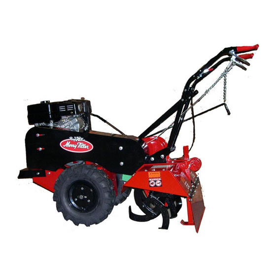
MERRY REAR TINE TILLER
RT1450IC - RT83H OWNER'S MANUAL
MACKISSIC, INC., P.O. BOX 111, PARKER FORD, PA 19457
Phone: (610) 495-7181
e-mail: info@mackissic.com
FAX: (610) 495-5951
www.mackissic.com
P/N 712-0078
05/11/17
Table of
Contents
Previous
Page
Next
Page
1
2
3
4
5
Advertisement
Table of Contents
Need help?
Do you have a question about the RT1450IC and is the answer not in the manual?
Ask a question
Questions and answers
Related Manuals for MACKISSIC RT1450IC
Tiller MACKISSIC RT83H Owner's Manual
Merry rear tine tiller (42 pages)
This manual is also suitable for:
Rt83h
Table of Contents
Print
Rename the bookmark
Delete bookmark?
Delete from my manuals?
Login
Sign In
OR
Sign in with Facebook
Sign in with Google
Upload manual
Upload from disk
Upload from URL


Need help?
Do you have a question about the RT1450IC and is the answer not in the manual?
Questions and answers