Table of Contents
Advertisement
Quick Links
Description
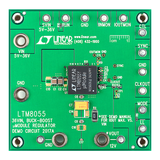
Demonstration circuit 2017A features the
buck-boost μModule
regulator that accepts input volt-
®
ages lower, higher or the same as the output, but is also
highly efficient due to its four-switch architecture. The
output for DC2017A is 12V and the input voltage range
is 5V to 36V. The maximum output current is 6A and the
switching frequency is 600kHz.
DC2017A supports the adjustable and controllable features
of the LTM8055 including output voltage and current
regulation, switching frequency, RUN threshold, soft-start
period, synchronization and reverse inductor current in-
hibit. In most cases, adjustment is made by modifying the
appropriate resistor or capacitor component(s). DC2017A
provides output current monitoring and a clock output.
performance summary
PARAMETER
Minimum Input Voltage, V
IN
Maximum Input Voltage, V
IN
Maximum Output Current, I
OUT
Input Turn-On Voltage, V
IN
Input Turn-Off Voltage, V
IN
Output Voltage, V
OUT
Efficiency
Switching Frequency
Output Current Limit
DEMO MANUAL DC2017A
LTM
8055, a
Input current monitoring and regulation requires the in-
®
stallation of a current sense resistor. The SV
controller power can be made a diode-OR of power V
and the output voltage to extend the operating range of
power V
optional components that add an LC input filter and also a
unity gain buffer to operate multiple DC2017As in parallel.
The LTM8055 data sheet must be read in conjunction with
this demo manual to properly use or modify DC2017A.
Design files for this circuit board are available at
http://www.linear.com/demo/DC2017A
L, LT, LTC, LTM, Linear Technology, µModule and the Linear logo are registered trademarks of
Linear Technology Corporation. All other trademarks are the property of their respective owners.
Specifications are at T
A
CONDITIONS
12V < V
< 36V, CTL = OPEN
IN
V
= 6V, CTL = OPEN
IN
R10 = 332k, R11 = 121k, V
Rising
IN
R10 = 332k, R11 = 121k, V
Falling
IN
100mA < I
< 6A, R2 = 11k, 1%
OUT
R3 = 100k 1%, R4 = 0.008Ω
V
= 24V, I
= 6A
IN
OUT
R1 = 36.5k
R4 = 0.008Ω
36V
, 8.5A Buck-Boost
IN
μModule
®
to lower voltages. There are places to mount
IN
= 25°C
MIN
36
6
3
11.72
LTM8055
Regulator
input for
IN
IN
TYP
MAX
UNITS
5
V
V
A
A
5.5
V
4.5
V
12.45
V
94
%
600
kHz
6.4
A
dc2017af
1
Advertisement
Table of Contents

Related Manuals for Linear Technology DC2017A


Summary of Contents for Linear Technology DC2017A
- Page 1 In most cases, adjustment is made by modifying the L, LT, LTC, LTM, Linear Technology, µModule and the Linear logo are registered trademarks of appropriate resistor or capacitor component(s). DC2017A Linear Technology Corporation. All other trademarks are the property of their respective owners.
- Page 2 DEMO MANUAL DC2017A BoarD photo Quick start proceDure To use DC2017A to evaluate the performance of the the V or V capacitors. See Figure 3 for proper scope LTM8055, refer to Figure 1 for the proper measurement probe technique. Solder terminals near the input or output equipment setup, Figure 2 for the maximum output current capacitors, if necessary.
- Page 3 DEMO MANUAL DC2017A Quick start proceDure – OPTIONAL – OPTIONAL WITH R7 = OPEN 3.3V – – 0V TO 36VDC – 12VDC 0A TO 6A – Figure 1. Proper Measurement Equipment Setup dc2017af...
- Page 4 DEMO MANUAL DC2017A Quick start proceDure R4 = SHORT R4 = 0.008 dc2017a F02 Figure 2. Maximum Output Current vs Input Voltage for V = 12V Figure 3. Proper Scope Probe Technique dc2017af...
- Page 5 DEMO MANUAL DC2017A Quick start proceDure -100 FREQUENCY (MHz) Figure 4. V Noise Spectrum (V = 24V, V = 12V at 6A) dc2017af...
- Page 6 DEMO MANUAL DC2017A parts List ITEM REFERENCE PART DESCRIPTION MANUFACTURER/PART NUMBER Required Circuit Components C1, C2 CAP., CER., 4.7µF, X7R, 50V, 10%, 1210 MURATA, GRM32ER71H475KA88L CAP., CER., 0.22µF, X7R, 16V, 10%, 0603 TDK, C1608X7R1C224K CAP., CER., 0.01µF, X7R, 16V, 10%, 0603...
- Page 7 Information furnished by Linear Technology Corporation is believed to be accurate and reliable. However, no responsibility is assumed for its use. Linear Technology Corporation makes no representa- tion that the interconnection of its circuits as described herein will not infringe on existing patent rights.
- Page 8 Linear Technology Corporation (LTC) provides the enclosed product(s) under the following AS IS conditions: This demonstration board (DEMO BOARD) kit being sold or provided by Linear Technology is intended for use for ENGINEERING DEVELOPMENT OR EVALUATION PURPOSES ONLY and is not provided by LTC for commercial use. As such, the DEMO BOARD herein may not be complete in terms of required design-, marketing-, and/or manufacturing-related protective considerations, including but not limited to product safety measures typically found in finished commercial goods.
Need help?
Do you have a question about the DC2017A and is the answer not in the manual?
Questions and answers