Table of Contents
Advertisement
Quick Links
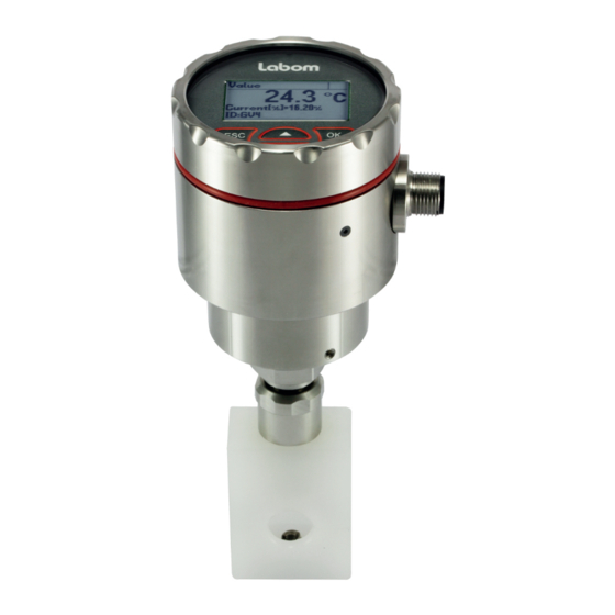
Temperature transmitter clamp-on
for temperature measurement on pipes,
Type series GV4610
Operating Instructions
1 General Information....................................................................................................... 2
1.1 General Safety Notes .............................................................................................. 2
1.2 Intended Use ........................................................................................................... 2
1.3 Conformity with EU Regulations .............................................................................. 2
2 Transportation and Storage .......................................................................................... 2
3 Installation and Commissioning .................................................................................. 2
3.1 Mechanical Installation ............................................................................................ 2
3.2 Mount / Dismount Display ....................................................................................... 4
3.3 Electrical Connection .............................................................................................. 5
3.4 Device orientation ................................................................................................... 5
3.5 Adjustment of the Display Contrast ......................................................................... 5
4 Operation ........................................................................................................................ 6
4.1 Calibration ............................................................................................................... 6
4.2 Maintenance / Service ............................................................................................. 6
5 Disassembly ................................................................................................................... 6
6 User Manual ................................................................................................................... 7
6.1 Basics of the Operating Concept ............................................................................. 7
6.2 Display Mode / Measured Value Display ................................................................. 8
6.3 Menue Mode / Operating Menue ........................................................................... 11
6.4 The Menue Tree .................................................................................................... 13
LABOM Mess- und Regeltechnik GmbH Im Gewerbepark 13 27798 Hude Germany
Hotline: +49 4408 804-444 Fax: +49 4408 804-100 e-mail: sales@labom.com www.labom.com
BA_084_2019-05_10.00
Page 1/20
Advertisement
Table of Contents

Subscribe to Our Youtube Channel
Related Manuals for Labom GV4610 Series


Summary of Contents for Labom GV4610 Series
-
Page 1: Table Of Contents
6.2 Display Mode / Measured Value Display ..............8 6.3 Menue Mode / Operating Menue ................11 6.4 The Menue Tree ....................13 LABOM Mess- und Regeltechnik GmbH Im Gewerbepark 13 27798 Hude Germany BA_084_2019-05_10.00 Hotline: +49 4408 804-444 Fax: +49 4408 804-100 e-mail: sales@labom.com www.labom.com... -
Page 2: General Information
In addition to this instruction, be sure to observe all statutory requirements, appli- cable standards, the additional technical specifications on the accompanying data sheet (see www.labom.com) as well as the specifications indicated on the type plate. General Safety Notes The installation, set up, service or disassembly of this device must only be done by trained, qualified personnel using suitable equipment and authorized to do so. - Page 3 3.1.1 Mounting the clamping element There are two options how to connect the device to the process: Figure 1: mounting options: a) clamping block, b) clamping shoe 3.1.1.1 Mounting the clamping block Required tools: Hexagon socket wrench 3 mm (mounting screws) Hexagon socket wrench 2 mm (vibration protection) ...
-
Page 4: Mount / Dismount Display
3.1.2 Mounting the measuring insert The mounting procedure for the measuring insert is identical for all clamping elements. First apply heat conductive paste to the tip of the measuring insert. Heat conductive paste is mandatory for this type series for a good measuring accuracy. Now insert the measuring insert into the bore in the clamping element. -
Page 5: Electrical Connection
Electrical Connection Complete the mechanical installation before you connect the device electrically. Set up all electrical connections while the voltage supply is switched off. Output (2-wire) 4...20 mA (20...4 mA) = 12…30 VDC Permissible supply voltage ≤ (U Permissible load - 12 V) / 22 mA Circular connector M12 Cable gland... -
Page 6: Operation
Operation During device operation, take care that the device remains within its intended temperature range. No other monitoring is necessary. -40…150 °C Permissible media temperature: -20…80 °C Permissible ambient temperature: Calibration We recommend an annual recalibration. Uninstall only the measuring insert. This way the measuring position remains unchanged as it is defined by the clamping element. -
Page 7: User Manual
User Manual The device can be configured via the display module as well as the HART protocol. The following pages describe operation and configuration of the device using the display mod- ule. An overview of the menue structure can be found on the last page of this document. Basics of the Operating Concept The display module consists of a dot-matrix display with 80x128 pixels as well as a... -
Page 8: Display Mode / Measured Value Display
The icon for the device status (see 6.2.3) is displayed in each operating mode. The con- tents of the header and the data area depend on the operating mode: Display of measured value Header: Icon description, if applicable. Otherwise "Value" ... - Page 9 The sequence of the screens with device data is as follows: Min/Max values (measurement) ----- Measured value display (starting point) --- Temperature measurement (senor type) Current output (characteristic curve, limits, measuring range) HART data (address, tag, descriptor) ...
- Page 10 6.2.4 Display layouts You can configure the layout of the measured value display as well as the displayed infor- mation individually. There are four different layouts available: Designation Layout Description Example Four values Under the main value, three additional values are shown. The 4th value can use the entire display width.
-
Page 11: Menue Mode / Operating Menue
Menue Mode / Operating Menue Press OK in the measured value display to go to the operating menue. Then the main menue appears in the display. In the operating menue you can navigate in the menues by using the arrow buttons. The selected menue item is indicated by triangles on the left and right. - Page 12 6.3.1 Displaying and entering parameters When entering parameters, either numerical inputs or a selection lists with fixed options is available. In general, the actual selection will be displayed first (view mode). Press OK to switch to edit mode to change the parameter. After this is done, the display will then switch back to view mode so that you can check the new setting.
-
Page 13: The Menue Tree
Numeric values are entered digit by digit. First, always the leftmost digit is selected (visible with a triangle above and below the number). By pressing OK, you go to the next digit. Figure 9: Elements when setting a numeric value You change the selected digit by pressing the button. - Page 14 6.4.1 Main menue The main menue has the following entries: Menue entry Description Quick setup Selection of the most important settings Adjustment Adjustment functions for temperature measurement and current output Display Functions for configuring the display Measurem./Output Configuration of the temperature measurement and current out- Diagnosis Diagnostic information such as min/max values Simulation...
- Page 15 6.4.3.1 Upper and lower adjustment The lower adjustment results in an offset of the characteristic curve. It thus affects the measuring range. The upper adjustment changes the slope of the characteristic curve by correcting the span of the measuring range. Execute the lower adjustment prior to the upper adjustment for a correct full adjustment.
- Page 16 6.4.4 "Display" menue In the "Display" menue, you find all the settings that affect the display on the screen. Menue entry Description Language Select menue language Units Setting units for the different measured and displayed values Screen mode Configuration of the screen layout and content (see 6.2.4) Decimal point Select setting of decimal places of the 1st value by specifying the decimal point...
- Page 17 6.4.5 Menue "Measurement/Output" Configure the measured value as well as the current output in the "Measurement/output" menue. Menue entry Description Output function Setting the output function (linear, inverse) Lower range val. Setting the temperature value that shall correspond to 4 mA (start of range) Upper range val.
- Page 18 6.4.7 Menue "Simulation" In the "Simulation" menue, you can simulate the temperature as well as the current to test the subsequent measuring chain. Menue entry Description Current sim. Setting a fixed current value Temperature sim. Setting a fixed temperature value Table 13: "Simulation"...
- Page 19 6.4.9.1 Device ID Using the device ID, you can show a custom text in the display if you configure the screen mode accordingly (see 6.2.4). For instance, you can show the tag number continuously in the display. The device ID can be up to 16 characters long and consist of numbers, empty spaces, capital letters and special characters.
- Page 20 6.4.10 Overview with menue tree and device functions BA_084_2019-05_10.00 Temperature transmitter clamp-on Page 20/20...
Need help?
Do you have a question about the GV4610 Series and is the answer not in the manual?
Questions and answers