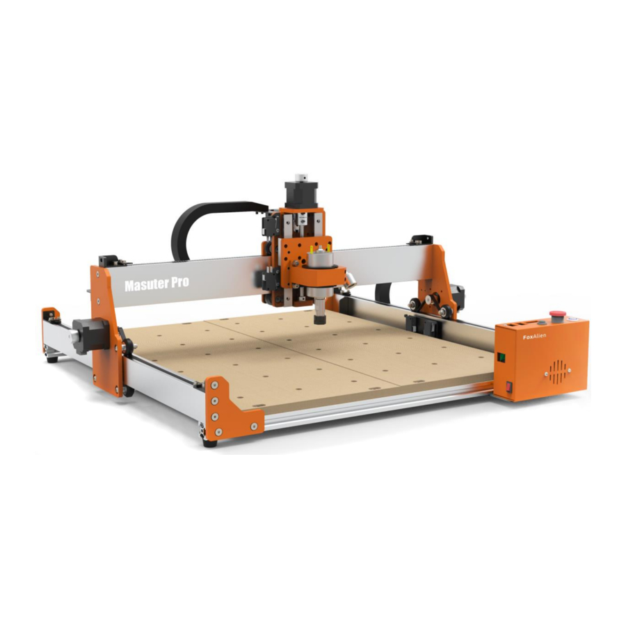
FoxAlien Masuter Pro - Desktop CNC Router Machine Manual
- User manual (32 pages)
Advertisement
- 1 Product Specifications
- 2 How to Assemble the Machine
- 3 Wiring Diagrams
- 4 Controller Instructions
- 5 How to Install the Router Bit
- 6 How to Use Grblcontrol (Candle)
- 7 Make Your First Cut
- 8 How to Unlock Limit Switch
- 9 How to Use E-stop
- 10 Z-Probe Operating
- 11 Extended Accessories
- 12 Documents / Resources
Product Specifications
| Model | Masuter Pro | ||||
| Working Area | 400 x 400 x 60mm (15.75" x 15.75" x 2.36") | ||||
| Input Voltage | 12V | ||||
| Input Current | 5A | ||||
| Spindle Power | 60W | ||||
| Spindle Speed | 10000 r/min | ||||
| Motor | NEMA17 | ||||
| Firmware Version | 1.1H | ||||
| Limit Switch | X, Y, Z | ||||
| Emergency Stop Button | Yes | ||||
| Support OS | Windows XP, Windows 7, Windows 8, Windows 10, Windows 11, Linux, Mac OS | ||||
| Software | Grblcontrol(Candle), other GRBL compatible software | ||||
| Offline Working | Supports offline working, offline control sold separately | ||||
| Support Add-ons | Laser, Offline controller, 300W Spindle& Trimmer (NOT included) | ||||
How to Assemble the Machine
Step 1
 Y-axis Aluminum Profile (L)
")
 Y-axis Aluminum Profile (R)
")
 X-axis Aluminum Profile

 M5*20 Flat Cap Bolt


Step 2
 MDF Spoil Board

 M5*20 Bolt


Step 3
 X-axis Gantry

 M5*16 Flat Cap Bolt


Step 4
 Spindle Holder

 M5*12 Bolt

 Washer


Step 5
 Spindle


Step 6
 Y-axis Drag Chain Bracket

 Y-axis Drag Chain Bracket

 M3*6 Button Cap Bolt


Step 7
 X-axis Drag Chain Bracket

 M3*6 Button Cap Bolt


Step 8
 Controller Support Plate

 Controller

 M3*8 Button Cap Bolt


Step 9
 M5*8 Bolt

 M5 T-nut


Step 10
 Hex Wrench


Step 11
 Y Axis Drag Chain

 M4*6 Flat Cap Bolt


Step 12
Y Axis Drag Chain
M4*6 Flat Cap Bolt

Wiring Diagrams
X, Y & Z Stepper Motors Wiring Diagrams

X, Y & Z Limit Switches Wiring Diagrams

Spindle & Light Wiring Diagrams

Positive wire (Red) connects to the port with red dot Negative wire (Blue) connects to the other port

60W spindle plugged into Spindle 1 socket Flip the toggle switch to the right side

Light: Insert the plug to the socket
Controller Instructions
Toggle Switch: Flip to the left when using 300W Spindle Flip to the right when using 60W Spindle or Laser

How to Install the Router Bit

How to Use Grblcontrol (Candle)
Driver Installation
- Download from U disk. Double-click to start installation.
![]()
- Click "INSTALL"
![]()
- Wait until it shows "Driver install success"
![]()
- Connect the USB cable to the PC and the cotroller.


To Determine your Machine's COM port
- For Windows XP: Right click "My Computer"→ Select "Manage"→ Select "Device Manager".
- For Windows 7: Right click "Computer"→ Select "Manage" → Select "Device Manager" from left pane.
- For Windows 10: Right click "This PC"→ Select "Manage" → Select "Device Manager" from left pane.
- In the tree, expand "Ports (COM & LPT)", your machine will be the USB Serial Port (COMX), where the "X" represents the COM number, for example COM6.
- If there are multiple USB serial ports, right click each one and check the manufacturer, the machine will be "CH340".
Grblcontrol (Candle) Working Interface Introduction
 Working Interface Introduction")
Make Your First Cut
- Double click to start Grblcontrol (Candle)
![]()
- Connect USB cable to computer and machine, click Service->Port select COM port. Click "OK"

- If Status becomes Alarm and [MSG: Check Limits] appears in the console at the same time, please check whether the limit switch is triggered. You can power off and elease the limit switch manually or refer the manual to release the limit via software.
![]()
- Console window prints "CTRL+X" indicates that the connection is failed. Need to check whether the E-stop is pressed down. If yes, turn the E-stop clockwise, and then click "Unlock".
![]()
- Console window prints "[CTRL+X] < Grbl 1.1f ['$' for help]" if the connection is successful. Click "Unlock".

- Fix the MDF with the clamps
![]()

- Open the file
- Choose the Step and Feed (Unit: mm)
- Click the direction button to move the bit to the surface of the object.
- The best distance between the bit and the object is that the bit should feel the A4 paper, and the paper can pass through the bit.
![]()

- Set origin. Click "Zero XY" and "Zero Z"
- Click "Send" to start engraving
- Engraving Finished.
![]()


How to Unlock Limit Switch
- Limit switch will trigger when the machine runs out of active working area.
![]()
- Command window will show: "ALARM:1 [MSG: Reset to continue]"
![]()
- Click "Reset"
![]()
- Click "Unlock"
![]()
- Click direction buttons to move the axis way from limit switch.
![]()
- If status change to "Alarm" again, that means it does not entirely move away from the limit switch, just repeat the previous steps to unlock.
![]()


How to Use E-stop
- Press down E-stop when the machine malfunctions to avoid damage.
![]()
- Rotate clockwise to release the E-stop.
![]()
- Status in software will change to "Alarm".
![]()
- Print "[MSG:'$H'|'$X' to unlock]"
![]()
- Click "Unlock" to normal working status.
![]()


Z-Probe Operating
- Connect the wire
![]()
- Measure Z probe actual size (Thickness: 14.83mm)
![]()
- Modify Z-probe parameter. Default value is Z15, change it to Z14.83 base of the parameter measured.

- Place the probe as shown
![]()
- Click "Zero XY"
![]()
- Click Z-probe button to start detecting. After Z-probe detection finished, remove Z-probe, click "Send" to start engraving.
![]()


Extended Accessories
(Available on foxalien.com)
Offline Controller

 Note: USB connection and offline controller can not be used at the same time.
Please unplug the USB cable when using the offline controller, otherwise it may cause errors, deviation or unusual stopping during engraving
Laser Module

Installation and Wiring Diagrams
300W Spindle

Flip the toggle switch to the left
300W spindle plugged into Spindle 2 socket

300W Spindle Installation and Wiring Diagrams
Please download the driver and software from the thumb drive included in the package.
It includes:
- CH340 Driver
- GrblControl (Candle) software for Windows
- Sample files
- PDF user manual
Or download the above documents from google drive link: https://shor.at/yeSs87LA
Please visit www.foxalien.com for more CNC machine accessories products.
Feel free to contact us for technical support if you come across any difficulty during assembly and using.
E-mail: aftersale@foxalien.com, support@foxalien.com
We will response within 1 business day.

Files Download

Facebook Group


Documents / Resources
References
![www.foxalien.com]() FoxAlien | Industry Leader in CNC & DIY Projects For Any Hobbyist
FoxAlien | Industry Leader in CNC & DIY Projects For Any Hobbyist![foxalien.com]() FoxAlien | Industry Leader in CNC & DIY Projects For Any Hobbyist
FoxAlien | Industry Leader in CNC & DIY Projects For Any Hobbyist
Download manual
Here you can download full pdf version of manual, it may contain additional safety instructions, warranty information, FCC rules, etc.
Download FoxAlien Masuter Pro - Desktop CNC Router Machine Manual
Advertisement


Need help?
Do you have a question about the Masuter Pro and is the answer not in the manual?
Questions and answers