
Related Manuals for FoxAlien Masuter


Summary of Contents for FoxAlien Masuter
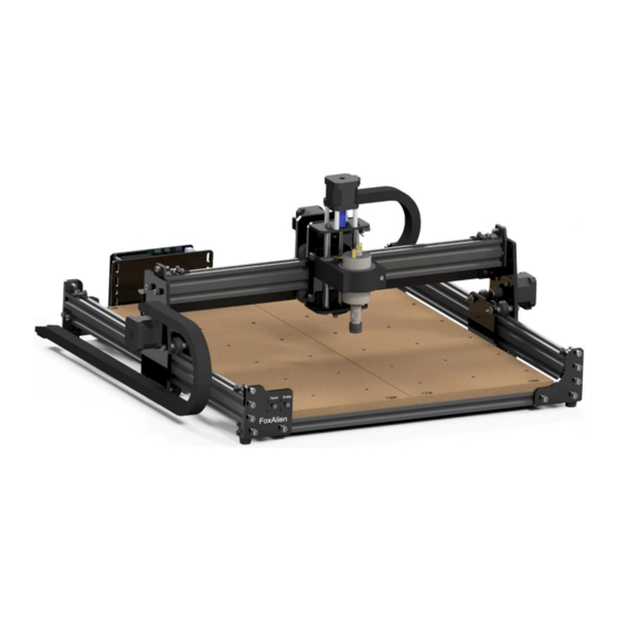
- Page 1 C N C R o u t e r M a s u t e r USER MANUAL Please read this manual carefully before using.
-
Page 2: Table Of Contents
Catalog Warranty & Disclaimer Product Specifications How to Assemble the Machine Wiring Diagrams • Control Board Wiring Diagrams • XYZ Stepper Wiring Diagrams • Limit Switch Wiring Diagrams • Spindle & Home/E-stop Button Wiring Diagrams Button Introduction How to Install the Router Bit How to Use Grblcontrol (Candle) •... -
Page 3: Warranty & Disclaimer
Warranty & Disclaimer Please be careful when using your CNC machine. This machine is an electrical device with moving parts and dangerous areas. • This CNC Machine is for Indoor Use Only. • Wear the proper protection equipment while operating. •... -
Page 4: Product Specifications
Product Specifications Model Masuter 400 x 380 x 55mm (15.75” x 14.96” x 2.16”) Working Area Input Voltage Input Current Spindle Power Spindle Speed 10000 r/min Motor NEMA17 Firmware Version 1.1H Limit Switch X, Y, Z Emergency Stop Button Support OS... -
Page 5: How To Assemble The Machine
How to Assemble the Machine Y-axis Aluminum Profile (Left) Y-axis Aluminum Profile (Right) X-axis Aluminum Profile... - Page 6 M5*16 Bolt M5*20 Bolt Washer Spring Washer Acrylic Sheet B Acrylic Sheet A Washer Spring Washer...
- Page 7 Base Frame Assembled...
- Page 8 MDF Waste Board...
- Page 9 M5*20 Bolt...
- Page 10 X-axis Gantry M5*12 Bolt Washer Spring Washer...
- Page 11 Z-axis Assembly M5*10 Bolt...
- Page 12 X-axis Drag Chain Bracket M5*10 Bolt -10-...
- Page 13 X-axis Drag Chain Bracket M5*6 Bolt -11-...
- Page 14 X-axis Drag Chain Bracket M5*6 Bolt T-nut -12-...
- Page 15 Y-Axis Drag Chain M4*6 Flat Head Cap Screw -13-...
- Page 16 X-Axis Drag Chain M4*6 Flat Head Cap Screw -14-...
- Page 17 Control Board M5*8 Bolt T-nut -15-...
-
Page 18: Wiring Diagrams
Wiring Diagrams X-axis Y2-axis Y1-axis Z-axis Spindle Laser USB Port Power on/off Offline Controller Port 12V 5A Power Supply X Limit Y Limit Z Limit E-Stop 12V Fan Home Switch Switch Switch probe -16-... -
Page 19: Control Board Wiring Diagrams
- Control Board Wiring Diagrams -17-... -
Page 20: Xyz Stepper Wiring Diagrams
- XYZ Stepper Motors Wiring Diagrams -18-... -
Page 21: Limit Switch Wiring Diagrams
- Limit Switches Wiring Diagrams -19-... -
Page 22: Spindle & Home/E-Stop Button Wiring Diagrams
- Spindle & Home/E-stop Button Wiring Diagrams Red wire connects to the port next to the red dot. Blue wire connects to the blue port White wire connects to the white port -20-... -
Page 23: Button Introduction
Button Introduction Home: Power on the machine, connect it to the software or offline controller, press Home button, the machine will go to the mechanical origin automatically. E-stop(Emergency stop switch): Press down the E-stop to abort the project when the machine malfunctions to avoid damage. After pressing the emergency stop switch, you can see that Click “Unlock”. -
Page 24: How To Install The Router Bit
How to Install the Router Bit Spindle Collet Loosen the cap Unlock the cap Insert a bit Tighten Fasten the cap -22-... -
Page 25: How To Use Grblcontrol (Candle)
How to Use Grblcontrol (Candle) Driver Installation 1. Download from U disk. 2. Click “INSTALL” 3. Wait until it shows “Driver install success” Double-click to start installation. 5. To Determine your Machine's COM port • For Windows XP: Right click "My Computer"→ Select "Manage"→... -
Page 26: Grblcontrol (Candle) Working Interface Introduction
Grblcontrol (Candle) Working Interface Introduction Coordinate display 3D preview interface, hold the Status display left mouse button, can rotate Common operation button, the mouse Angle, scroll the mouse icon on the above shows the specific wheel, can be enlarged, function or reduced. -
Page 27: Make Your First Cut
Make Your First Cut Double click to start Grblcontrol (Candle) Console window prints “[CTRL+X] < Grbl 1.1f [‘$’ Connect USB cable to PC and control board. for help]” if the connection is successful. Click Service->Port select COM port. Click “OK” If the Status displays Alarm and Console print... - Page 28 Open a G-code file, Preview G-Code Choose the Step and Feed (Unit: mm) Click the direction button to move the bit to the surface of the object. The best distance between the bit and the object is that the bit should feel the Engraving Finished.
-
Page 29: Z-Probe Operating
Z-Probe Operating Modify Z-probe parameter. Default value is Z15, change it to Z14.83 base of the parameter measured. Thickness: 14.83mm Click Z-probe button to start detecting. Click ”Zero XY” After Z-probe detection finished, Place the probe as shown remove Z-probe, click “Send” to start engraving. -
Page 30: Extended Part
Extended Part - Offline Controller USB and offline controller cannot be used at the same time. So when using the offline controller, please unplug the USB cable, otherwise it may cause errors, deviation or unusual stopping during engraving. - Laser Module Tighten the screws Installation steps... - Page 31 GrblControl (Candle) software for Windows & Mac OS • Sample files Please visit www.foxalien.com for more CNC machine accessories products. Feel free to contact us for technical support if you come across any difficulty during assembly and using. E-mail: support@foxalien.com We will response within 1 business day.
Need help?
Do you have a question about the Masuter and is the answer not in the manual?
Questions and answers
How do I set up z probe on fox Alien masuter 3s using UGCS on a Mac
1. Connect the Z probe to the back of the control box.
2. Open UGCS (Universal G-Code Sender) on your Mac.
3. Move the bit to the surface of the object using the direction buttons.
4. Place an A4 paper under the bit; it should barely touch the paper.
5. Click "Zero XY" and "Zero Z" to set the origin.
6. Modify the Z-probe parameter in UGCS, changing Z15 to Z14.83.
7. Place the Z probe as shown in the manual and click the Z-probe button to start detection.
8. After detection, remove the Z probe and click "Send" to start engraving.
This answer is automatically generated