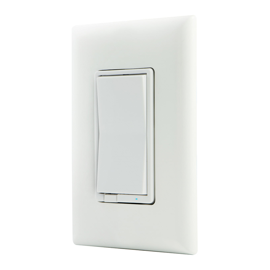
Honeywell ZW4005 - Smart Switch Manual
- Manual (2 pages) ,
- Quick start manual (2 pages)
Advertisement
SAFETY

RISK OF FIRE RISK OF ELECTRICAL SHOCK RISK OF BURNS CONTROLLING APPLIANCES:

- DO NOT EXCEED RATINGS
- DO NOT USE TO CONTROL ANY DEVICE WHERE UNINTENDED OPERATION COULD CAUSE UNSAFE CONDITIONS (HEAT LAMP, SUN LAMP, ETC.)
- DO NOT USE TO CONTROL RECEPTACLES
- FOR INDOOR USE ONLY
TOOLS


The fixture controlled by the Z-Wave In-Wall Smart Switch must not exceed 960 watts (Incandescent); 1800W (15A) Resistive or ½ HP Motor. The switch is designed only for use with permanently installed fixtures.
FEATURES
- Turn ON/OFF manually or remotely via the Z-Wave controller
- Can be added in multiple groups and scenes
- May be used in single pole installation or with up to two Honeywell Add-on switches in 3-way or 4-way wiring configurations
- Compatible with all incandescent and CFL/LED bulbs
- Interchangeable paddle switch — white & light almond paddle in package
- Uses a standard, decorative-size wallplate for single gang installations (wallplate not included)
- Blue LED indicates switch location in a dark room
- Z-Wave Certified for simple pairing and integrated home automation
- Screw Terminal Installation — requires wiring connections for Line (Hot), Load, Neutral and Ground. Traveler wire required for 3-way or 4-way installation
- This Z-Wave device has advanced features that allow you to customize your experience. These features can only be adjusted by a Z-Wave enabled controller that support the Z-Wave Configuration command class. For a complete list of adjustable configurations, visit: www.honeywellelectricalaccessories.com.


- Ground (Green/Bare)
- Load (Black)
- Line (Black)
- Traveler (Red/Other)
- Neutral (White)
- Top Rocker — Press & release to turn switch ON
- Bottom Rocker — Press & release to turn switch OFF
SINGLE-, DUAL- AND TRIPLE-GANG BOXES
When installing the In-Wall smart switch in multiple gang boxes it may be necessary to break off one or both sides of the scored tabs on the front yoke. This does not affect the electrical rating of the smartswitch (see specifications for details).

SHOCK HAZARD
Turn OFF the power to the branch circuit for the switch and lighting fixture at the service panel. All wiring connections must be made with the POWER OFF to avoid personal injury and/or damage to the switch. This device is intended for installation in accordance with the National Electric Code and local regulations in the United States, or the Canadian Electrical Code and local regulations in Canada. If you are unsure or uncomfortable about performing this installation consult a qualified electrician.
MULTI-SWITCH WIRING
The Honeywell Add-on switch is required for Multi-Switch 3-way or 4-way installations. Connecting the traveler terminal of this switch to a standard, non-Honeywell switch will cause damage or result in improper function. If this switch is a part of a 3-way or 4-way multi-switch installation, do not connect the traveler wire or apply power until Honeywell Add-on switches are correctly installed. For more information on 3-Way or 4-Way installations, view the manual or quick-start guide that comes with the Honeywell Add-on switch.
SINGLE-SWITCH WIRING
Before you start; you may wish to change the paddle color to match your wallplate or decor. Please proceed to CUSTOMIZATION.
- Shut off power to the circuit at circuit breaker or fuse box.


Verify power is OFF to switch box before continuing.
- Remove wallplate.

- Remove the switch mounting screws.

- Carefully remove the switch from the switch box. DO NOT disconnect the wires.
- There are up to five screw terminals on the switch; these are marked
- GROUND — Green/Bare
- LOAD — Black (connected to lighting)
- LINE (Hot) — Black (connected to power)
- TRAVELER — Red/Other (only in 3-way installations)
- NEUTRAL — White
Match these screw terminals to the wires connected to the existing switch.

- Disconnect the wires from the existing switch. Be careful to label wires according to the previous terminal connection.


OBSERVE IMPORTANT WIRING INFORMATION
This switch is rated for and intended to only be used with copper wire.
WIRE GAUGE REQUIREMENTS
Use 14 AWG or larger wires suitable for at least 80°C for supplying Line (HOT), Load, Neutral, Ground and Traveler connections.
WIRE STRIP LENGTH
- For attachment to screw terminals: strip insulation 1" (25mm)
For attachment using the enclosure's holes:
strip insulation 5/8" (16mm)

UL specifies that the tightening torque for the screws is 14 Kgf-cm (12 lbf-in). - Connect the green or bare copper ground wire to the GROUND terminal.

- Connect the black wire that goes to the light to the terminal marked LOAD.
- Connect the black wire that comes from the electrical service panel (Hot) to the terminal marked LINE.
- Connect the white wire to the neutral terminal (use a jumper wire if needed).
Note: The Traveler terminal is only used for 3-way or 4-way wiring and should remain insulated if the switch is being installed in a single pole installation (one switch & one load). - Insert switch into the switch box being careful not to pinch or crush wires.
- Secure the switch to the box using the supplied screws.

- Mount the wallplate.

- Reapply power to the circuit at fuse box or circuit breaker and test the system.


BASIC OPERATION
The connected light can be turned ON/OFF in two ways:
- Manually from the front panel of the In-Wall Switch.
- Remotely with a Z-Wave Controller..
MANUAL CONTROL
The front panel rocker switch allows the user to turn ON/OFF the connected fixture.
- To turn the connected fixture ON: press and release the top of the rocker.
- To turn the connected fixture OFF: press and release the bottom of the rocker.
DISABLE / ENABLE LED
- Press UP three (3) times then quickly press and release DOWN one (1) time.
- Repeat to disable/enable LED.
CONNECTION

CONNECTING YOUR DEVICE TO A Z-WAVE NETWORK
- Follow the instructions for your Z-Wave certified controller to add a device to the Z-Wave network.
- Once the controller is ready to add your device, press and release the top or bottom of the wireless smart switch (rocker) to add it in the network.
Now you have complete control to turn your fixture ON/OFF according to groups, scenes, schedules and interactive automations programmed by your controller.
If your Z-Wave certified controller features remote access, you can now control your fixture from your mobile devices.
REMOVING AND RESETTING THE DEVICE
- Follow the instructions for your Z-Wave certified controller to remove a device from the Z-Wave network.
- Once the controller is ready to remove your device, press and release the top or bottom of the wireless smart switch (rocker) to remove it from the network.
RETURNING SWITCH TO FACTORY DEFAULTS
Quickly press ON (Top) button three (3) times then immediately press the OFF (Bottom) button three (3) times. The LED will flash ON/OFF 5 times when completed successfully.
Note: This should only be used in the event your network's primary controller is missing or otherwise inoperable.
CUSTOMIZATION

CHANGING THE COLOR OF THE PADDLE
This step is optional. Before you start you may want to change the color of the paddle to match your wallplate or decor.
- Lift the air gap tab at the base of the paddle.
- Push side tabs in on one side and then the other to release paddle. Lift the cover up and off.
- Simply put the new paddle onto the switch by inserting the air gap and side tabs and snapping securely into place.
Once this step has been completed please return to Installation.
SPECIFICATIONS
ZW4005
Power: 120 VAC, 60 Hz.
Signal (Frequency): 908.4 / 916 MHz
Maximum Loads: 960W, incandescent, ½ HP Motor or 1800W (15A) Resistive Range: Up to 150 feet line of sight between the Wireless
Controller and the closest Z-Wave receiver module.
Operating Temperature Range: 32-104°F (0-40°C) For indoor use only.
Specifications subject to change without notice due to continuing product improvemen

Documents / Resources
References
Download manual
Here you can download full pdf version of manual, it may contain additional safety instructions, warranty information, FCC rules, etc.
Advertisement


Need help?
Do you have a question about the ZW4005 and is the answer not in the manual?
Questions and answers