TE Connectivity Integra INT-2270, INT-2170 - Multifunction Digital Meter Technical Manual
- Technical instructions (2 pages)
Advertisement
Introduction
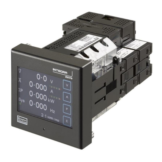
The Integra, INT-2270 and Integra INT-2170, are a multifunction digital meter for the measurement of power quality. They provide measurement isolation and conversion of all main electrical parameters. Both INT-2270 and INT-2170 can be used in single and three-phase balanced or unbalanced, 3 or 4 wire electrical systems.
The INT-2270 has an accuracy of CL0.2S.
The INT-2170 has an accuracy of CL0.5S.
Both include RS485 Modbus RTU communications protocol and Pulse/Alarm input/outputs as standard.
Measurement
The device is supplied programmed to the users requirements but can be easily reprogrammed to suit any application.
Setup
The Integra, INT-2*70, is individually calibrated to full accuracy. No further adjustments or setup is required.
Should the unit need reprogramming please refer to the Programming Guide for further information.

Warnings

Risk of Electric Shock
- During normal operation, voltages hazardous to life may be present at some of the terminals of this unit.
- At voltages below that specified in the Range of Use the meter may shut down. However, voltages hazardous to life may still be present at some of the terminals of this unit.
- Installation and servicing should be performed only by qualified, properly trained personnel abiding by local regulations.
- Ensure all supplies are de-energised before attempting connection or other procedures.
- Terminals should not be user accessible after installation and external installation provisions must be sufficient to prevent hazards under fault conditions.
- This unit is not intended to function as part of a system providing the sole means of fault protection - good engineering practice dictates that any critical function be protected by at least two independent and diverse means.
- The unit does not have internal fuses therefore external fuses must be used for protection and safety under fault conditions.
- Never open-circuit the secondary winding of an energized current transformer.
- This product should only be operated with the CT secondary connections earthed.
- If this equipment is used in a manner not specified by the manufacturer, protection provided by the equipment may be impaired.
- During installation suitable PPE, including eye protection MUST be worn at all times.
Safety
The unit is designed in accordance with BS EN 61010-1:2001 (IEC 61010-1:2001) – Permanently connected use, Normal condition. Installation category III, pollution degree 2, basic insulation for rated voltage. Measurement Category III.
Maintenance
In normal use, no maintenance is needed. As appropriate for service conditions, isolate from electrical power, inspect the unit, and remove any dust or other foreign material present. Periodically check all connections for freedom from corrosion and screw tightness, particularly if vibration is present.
The front of the case should be wiped with a dry cloth only. Use minimal pressure, especially over the viewing window area. If necessary wipe the rear case with a dry cloth. If a cleaning agent is necessary, isopropyl alcohol is the only recommended agent and should be used sparingly. Water should not be used. If the rear case exterior or terminals should be contaminated accidentally with water, the unit must be thoroughly dried before further service. Should it be suspected that water might have entered the unit, factory inspection and refurbishment is recommended.

It is essential that the primary current is isolated BEFORE connecting or disconnecting the secondary current connections
The unit is intended for panel mounting. Avoid mounting the unit where there is excessive vibration; in excessive direct sunlight; or outside a reasonably stable ambient temperature.
Connection Diagram


CONNECTION DETAIL
 REFER TO MANUAL
EMC Installation Requirements
Whilst this unit complies with all relevant EU EMC (electromagnetic compatibility) regulations, any additional precautions necessary to provide proper operation of this and adjacent equipment will be installation dependent and so the following can only be general guidance:
- Avoid routing wiring to this unit alongside cables and products that are, or could be, a source of interference.
- The supply to the unit should not be subject to excessive interference. In some cases, a supply line filter may be required.
- To protect the product against incorrect operation or permanent damage, surge transients must be controlled. It is good EMC practice to suppress transients and surges at the source. The unit has been designed to automatically recover from typical transients; however in extreme circumstances it may be necessary to temporarily disconnect the supply for a period of greater than 10 seconds to restore correct operation.
- Screened communication leads are recommended and may be required. These and other connecting leads may require the fitting of RF suppression components, such as ferrite absorbers, line filters etc., if RF fields cause problems.
- It is good practice to install sensitive electronic instruments that are performing critical functions in EMC enclosures that protect against electrical interference causing a disturbance in function.
Wiring
Connections are made via shrouded screw-clamp 0.05-4mm wire. Choice of cable should meet local regulations for the operating voltage.
Connector plugs are suitable for copper wires only and will accept one stranded 0·05 – 4mm2 (30 - 11AWG) stranded core cables. This instrument is intended for panel mounting. Terminals must be enclosed within the panel. For mains terminals use wire rated at 1000V, 60°C minimum temperature. Terminal screws are fully tightened for shipment and must be undone before wire insertion. Terminal screws should be tightened to 0·5 Nm (4·4 lbf in) only.
Fusing
This unit must be installed with external fuses in the voltage supply lines of type slow blow 1A maximum. Choose fuses of a type and with a breaking capacity appropriate to the supply and in accordance with local regulations.
A suitable switch or circuit breaker conforming to the relevant parts of IEC 60947-1 and IEC 60947-3 should be included in the installation. It should be positioned so as to be easy to operate, in close proximity to the equipment, and clearly identified as the disconnecting device.
Specification
| System Input | |
| Nominal input voltage | 57.7 to 364V AC L-N (100 – 600V AC L-L) 720V MAX |
| Max. continuous input overload voltage | 120% of nominal |
| Max. short duration input Voltage | 2 x range maximum |
| Nominal input voltage burden | < 0·2VA all phases |
| Nominal input current | 1 or 5 A |
| Max. short duration input current | 20 x nominal (for 300msec) |
| Frequency | 45 to 65Hz |
| Supply burden | 10 VA |
| Range of Use Values of measured quantities, components of measured quantities, and quantities which affect measurement errors to some degree, for which the product gives meaningful readings: | |
| Voltage | 5... 120% of nominal |
| Current | 5... 120% of nominal |
| Active power | 50... 120% of nominal |
| Apparent power | 50... 120% of nominal |
| Power is only registered when voltage and current are within their respective range of use. | |
| Accuracy (INT-2270) | |
| Voltage (V) | < 0·2% of reading |
| Current (A) | < 0·2% of reading |
| Neutral current calculated (A) | < 1% of reading |
| Frequency (Hz) | < 0.1 Hz |
| Active power (W) | ± 0.2% of reading CL0.2S |
| Reactive power (VAr) | ± 0.2% of reading CL0.2S |
| Apparent power (VA) | ± 0.2% of reading CL0.2S |
| Active energy (kWh) | Class 0.2 (IEC 62053-21) section 4.61 |
| Reactive energy (kVArh) | Class 1 IEC 62053-23 2 |
| THD | up to 63rd harmonic |
| Accuracy (INT-2170) | |
| Voltage (V) | < 0·5% of reading |
| Current (A) | < 0·5% of reading |
| Neutral current calculated (A) | < 1% of reading |
| Frequency (Hz) | < 0.1 Hz |
| Active power (W) | ± 0.5% of reading CL0.5S |
| Reactive power (VAr) | ± 0.5% of reading CL0.5S |
| Apparent power (VA) | ± 0.5% of reading CL0.5S |
| Active energy (kWh) | Class 0.5 (IEC 62053-21) section 4.61 |
| RS485 / Modbus RTU output | |
| Type | 2-wire half duplex |
| Baud rate | 9600, 19200, 38400 |
| *Ensure any external circuits connected to RS-485 output modules are provided with double/reinforced insulation. | |
| Pulsed Output Two voltage-free pulse outputs for measuring active and reactive energy. The pulsed output is used as an option with Alarm Outputs. | |
| Output Type | Solid State Relay |
| Contact Rating | 50mA max at 250V AC |
| Isolation | 2.5 kV |
| Pulsed Duration | 60, 100, 200mSecs |
| Pulsed Rate Divisors Range | 1 pulse per Wh up to 1 pulse per GWh |
| Pulsed Output Allocation | Import / Export kWh / KVArh |
| Energy Units | Unit, Kilo, Mega, Giga |
| Limited Max Pulse rate | 2 pulses per sec |
| Alarm Output Used instead of pulsed outputs in any configuration. | |
| Type | User defined Solid State Relay |
| Pulse duration | 30msec to 1000 msec |
| Alarm Delay | 0-120 secs |
| Hysteresis | 1 – 99% |
| Inputs Pulsed inputs from a galvanically isolated open collector source. | |
| Input Voltage Range | 0 to 24V DC |
| Input current (max) | 2.0 mA @ 24V DC |
| Switch response time | 0.5 secs (Latency to respond to pulse event) |
| Pulse frequency (max) | 25Hz (20ms) |
| Reference Conditions of Influence Quantities Influence Quantities are variables that affect measurement errors to a minor degree. Accuracy is verified under nominal value (within the specified tolerance) of these conditions. | |
| Ambient temperature | 23°C ±1°C |
| Input waveform | 50 or 60Hz ±2% |
| Input waveform | Sinusoidal (distortion factor<0·005) |
| Magnetic field of external origin | Terrestrial flux |
| Environment | |
| Operating temperature | -20°C to +60°C* |
| Storage temperature | 30°C to +80°C* |
| *Maximum operating and storage temperatures are in the context of typical daily and seasonal variation. | |
| Relative humidity | 0 to 95%, non-condensing |
| Altitude | Up to 2000m |
| Warm up time | 1 minute |
| Vibration | 10Hz to 50Hz, IEC 60068-2-6, 2g |
| Shock | 30g in 3 planes, IEC 60068-2-6, 2g |
| Dielectric voltage | 2.5kV, 50Hz for 1 minute |
| Withstand test | supply/inputs/outputs |
| Mechanics | |
| Dimensions | 96 x 96 DIN 4.3" x 4.3" ANSI |
| Depth | Front of Panel19.9mm (0.78") Rear of Panel 78.3mm (3.00") |
| Sealing | IP52 (front panel), IP30 (rear) |
| Mounting | Panel Mounted DIN96, ANSI |
| Cutout | DIN 96 92mm x 92mm square ANSI C39.1 4" round |

Standards and Approvals
| Electromagnetic compatibility | |
| Electrostatic discharge | IEC 61000-4-2 |
| Immunity to radiated fields | IEC 61000-4-3 |
| Immunity to fast transients | IEC 61000-4-4 |
| Immunity to Impulse waves | IEC 61000-4-5 |
| Conducted immunity | IEC 61000-4-6 |
| Immunity to magnetic fields | IEC 61000-4-8 |
| Immunity to voltage dips | IEC 61000-4-11 |
| IEC 61326-1, Class A | |
| Accuracy | |
| Static meter for active energy (Class 0.2S) | IEC 62053-21 IEC 62053-22 |
| Active energy accuracy | ANSI C12.20 |
| Static meter for reactive energy (Class 0.5S) | IEC 62053-23 |
| Safety | |
| CE Marking | IEC 61010-1 Ed.3 IEC 62052-11 |
| Features | |
| Sag / Swell | IEC 50160 |
Explanation of Symbols
| Refer to manual |
 | Danger of electric shock |
 | Do not discard |
While TE has made every reasonable effort to ensure the accuracy of the information in this catalogue, TE does not guarantee that it is error-free, nor does TE make any other representation, warranty or guarantee that the information is accurate, correct, reliable or current. TE reserves the right to make any adjustments to the information contained herein at any time without notice. TE expressly disclaims all implied warranties regarding the information contained herein, including, but not limited to, any implied warranties of merchantability or fitness for a particular purpose. The dimensions in this catalogue are for reference purposes only and are subject to change without notice. Specifications are subject to change without notice. Consult TE for the latest dimensions and design specifications. TE connectivity (logo), TE (logo) and TE Connectivity are trademarks of the TE Connectivity Ltd. family of companies. Crompton is a trademark of Crompton Parkinson and is used by TE Connectivity under a licence. Other logos, product and company names mentioned herein may be trademarks of their respective owners
TE Energy – innovative and economical solutions for the electrical power industry: cable accessories, connectors & fittings, insulators & insulation, surge arresters, switching equipment, street lighting, power measurement and control.
Tyco Electronics UK Ltd
TE Energy
Freebournes Road
Witham, Essex CM8 3AH
Phone: +44 (0)870 870 7500
Fax: +44 (0)870 240 5289
Email: Crompton.info@te.com

Documents / Resources
References
Download manual
Here you can download full pdf version of manual, it may contain additional safety instructions, warranty information, FCC rules, etc.
Download TE Connectivity Integra INT-2270, INT-2170 - Multifunction Digital Meter Technical Manual
Advertisement


Need help?
Do you have a question about the Integra INT-2270 and is the answer not in the manual?
Questions and answers