Advertisement
Quick Links
Installation and
Operating Instructions
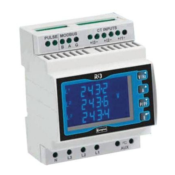
Integra Ri3
DIN-rail digital meter for single
and three-phase electrical systems
Caution:
consult instructions before installation or use
Introduction
This unit measures and displays the characteristics of single-phase
two-wire, three-phase three-wire and three-phase four-wire
supplies, including voltage, frequency, current, power and real and
reactive energy, imported and exported.
For more in-depth operating instructions, please refer to the full
manual that is available on the Crompton Instruments website, at
www.crompton-instruments.com.
Measurement
In measurement mode, the buttons control the displayed
measurement as follows:
Selects the Voltage and Frequency display screens.
Successive operations of the button select voltage,
frequency and %THD (Total Harmonic Distortion).
In Set-up mode, this is the 'Back' button.
Selects the Current display screens. Successive
operations select phase and neutral (3ph4w) currents,
max. demanded currents and current %THD.
In Set-up mode, this is the 'Up' button.
Selects the Instantaneous Power screens. Successive
operations select power (W, VAr & VA), max.
demanded power and power factor.
In Set-up mode, this is the 'Down' button.
Selects the Energy display screens. Successive
operations select imported/exported Wh and Varh.
Display can indicate up to 9999999·9.
Running man symbol flashes as data accumulates.
1% symbol shows that power values of <1% of range
maximum will be included in energy readings.
In Set-up mode, this is the 'Enter' button.
Display shows the units of measurements in use for each range.
Energy units can be set via set-up screens; other units are set
automatically.
A Demand Reset resets maximum demand readings to zero.
Setting up
To enter set-up mode, firmly press the
simultaneously and hold for 5 seconds, until the password screen
appears. Setting up is password-protected so you must enter the
correct password (default '0000') before proceeding. If an incorrect
password is entered, the display reverts to measurement mode.
To exit setting-up mode, press
measurement screen is restored or hold
simultaneously for 5 seconds.
and
buttons
repeatedly until the
and
buttons
Setup Menu Structure
Change password
nnnn – 4-digit number, default '0000'.
Supply system
3-phase 3-wire or 4-wire or single phase.
CT Set the value of the CT primary in use
nnnn – 4-digit number, 0001 to 9999.
dIT - Demand Integration Time
This is the period in minutes over which the current and power
readings are integrated for maximum demand measurement.
Options are: Off, 5, 8, 10, 15, 20, 30 and 60 minutes.
RSET
Resets cumulative Energy and/or Demand
measurements to zero.
COMS
Communication parameters for RS485 interface:
FMT – Format:
Modb Modbus protocol,
Baud rate 2400/4800/9600/19200/38400
Parity none/odd/even
Stop bits 1 (1 or 2 if parity is None)
Network address nnn – 3-digit number, 1 to 247
Order: Norm/Rev – Indicates Modbus word order.
N2
Johnson Controls (JC) N2 protocol,
Network address nnn – 3-digit number, 1 to 255.
Rly - Relay pulse output
kWh/kVArh (Active/reactive) Import or Export
Rate 0.001/0.01/0.1/1/10/100/1k/10k kWh or kVArh per pulse
Pulse width 200/100/60 ms.
NRGy - Energy
Unit/kilo/Mega units selection
1% limit on/off. If on, power values <1% of range max. will not
be included in energy measurements (prevents 'creep').
Test
Display on – all elements on to check display
dISTG – Display toggle. Each element is turned on and off
Phase sequence (V123 I123).
SOFT
Displays firmware version and build numbers.
Menu Option Selection
1.
Use the
(up) and
item from the menu. Selection does not roll over between
bottom and top of list.
2.
Press
to confirm the selection.
3.
If an item flashes, then it can be adjusted by the
(down) keys. If not, there may be a further layer, e.g.
Comms - Baud rate, before adjustment is possible. Press
to select the lower layer.
4.
Having selected an option from the current menu layer, press
to confirm your selection. The SET indicator will appear.
5.
Having completed a parameter setting, press
a higher menu level. The SET indicator will be removed and
you will be able to use the
menu selection.
6.
On completion of all setting-up, press
measurement screen is restored.
Number Entry Procedure
When setting up the unit, some screens require the entering of a
number. In particular, on entry to the setting up section, a
password must be entered. Digits are set individually, from left to
right. The procedure is as follows:
1.
The current digit to be set flashes and is set using the
(up) and
(down) keys.
2.
Press
to confirm each digit setting. The SET indicator
appears after the last digit has been set.
3.
After setting the last digit, press
setting routine. The SET indicator will be removed.
(down) keys to select the required
(up) and
to return to
and
keys for further
repeatedly until the
to exit the number
Advertisement

Related Manuals for TE Connectivity Integra Ri3


Summary of Contents for TE Connectivity Integra Ri3
- Page 1 Operating Instructions Options are: Off, 5, 8, 10, 15, 20, 30 and 60 minutes. RSET Resets cumulative Energy and/or Demand measurements to zero. Integra Ri3 COMS Communication parameters for RS485 interface: FMT – Format: Modb Modbus protocol, DIN-rail digital meter for single...
- Page 2 Installation Danger: Risk of Elecric Shock During normal operation, voltages hazardous to life may be present at some of the terminals of this unit. Installation and servicing should be performed only by qualified, properly trained personnel abiding by local regulations.
- Page 3 Measured Inputs Fusing Voltage inputs through 4-way fixed connector with 2·5mm² This unit must be fitted with external fuses in voltage and auxiliary (12AWG) stranded wire capacity. 3-Phase 3- & 4-wire, and Single- supply lines. Voltage input lines must be fused with a quick blow phase 2-wire.
- Page 4 UL61010-1 While TE Connectivity (TE) has made every reasonable effort to ensure the accuracy of the information in this catalog, TE does not guarantee that it is error-free, nor does TE make any other representation, warranty or guarantee that the information is accurate, correct, reliable or current.
Need help?
Do you have a question about the Integra Ri3 and is the answer not in the manual?
Questions and answers