Table of Contents
Advertisement
Quick Links
User Manual
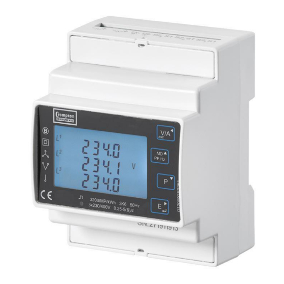
DRS-CT-3P-MOD-2T
DIN Rail Energy Meter for CT Connected
Three Phase Electrical Systems
DUAL TARRIF
Caution: Risk of
Warnings
Electric Shock
During normal operation, voltages hazardous to life
may be present at some of the terminals of this unit.
At voltages below that specified in the Range of Use
the meter may shut down. However, voltages
hazardous to life may still be present at some of the
terminals of this unit.
Installation and servicing should be performed only
by qualified, properly trained personnel abiding by
local regulations.
Ensure
all
supplies
are
de-energised
before
attempting connection or other procedures.
Terminals should not be user accessible after
installation and external installation provisions must
be
sufficient
to
prevent
hazards
under
conditions.
This unit is not intended to function as part of a
system providing the sole means of fault protection -
good engineering practice dictates that any critical
function be protected by at least two independent and
diverse means.
The unit does not have internal fuses therefore
external fuses must be used for protection and safety
under fault conditions.
Never open-circuit the secondary winding of an
energized current transformer.
This product should only be operated with the CT
secondary connections earthed.
If this equipment is used in a manner not specified by
the
manufacturer,
protection
provided
by the
equipment may be impaired.
1 Introduction
This document provides operating, maintenance and installation
instructions. This unit measures and displays the characteristics
of Single Phase Two Wire (1P2W), Three Phase Three Wire
(3P3W) and Three Phase Four Wire (3P4W) networks. The
measuring parameters include Voltage (V), Current (A),
Frequency (Hz), Power (kW/KVA/KVAr), Power Factor (PF),
Imported, Exported and Total Energy (kWh/kVArh).The unit also
measures Maximum Demand Current and Power, this is
measured over preset periods of up to 60 minutes.
It also comes with a complete comms capability with built in
Pulse and RS485 Modbus RTU outputs, configuration is
password protected.
This unit is 1A or 5A current transformer operated.
Auxiliary powered.
1.1 Unit Characteristics
The DRS-CT-3P can measure and display:
• Phase to Neutral Voltage and THD% (Total
Harmonic Distortion) of all Phases
• Line Frequency
• Current, Maximum Demand Current and Current
THD% of all Phases
• Power, Maximum Power Demand and Power Factor
• Imported, Exported & Total Active Energy
• Imported, Exported & Total Reactive Energy
The unit has a Password-Protected set up menu for:
fault
• Changing the Password
• System Configuration - 1P2W, 3P3W, 3P4W.
• Demand Interval Time
• Reset for Demand Measurements
• Pulsed Output Duration
1.2 RS485 Serial – Modbus RTU
RS485 serial port with Modbus RTU protocol to provide a means
of remotely monitoring and controlling the Unit. Set-up screens
are provided for setting up the RS485 port. Refers to section 4.8.
1.3 Pulse output
Two pulsed outputs that can be set for active (kWh) or reactive
(kVArh) energy.
2 Start Up Screens
The first screen lights up all
display segments and can be used
as a display check.
The second screen indicates the
firmware installed in the unit and
its build number.
Please note: Values may vary from
the numbers shown here.
The interface performs a self-test
and indicates the result if the test
passes.
*After a short delay, the screen will display active energy
measurements.
3 Measurements
The buttons operate as follows:
Selects the Voltage and Current display screens. In
Set-up Mode, this is the "Left" or "Back" button.
Select the Frequency and Power factor display
screens. In Set-up Mode, this is the "Up" button.
Select the Power display screens.
In Set-up Mode, this is the "Down" button.
Select the Energy display screens. In Set-up mode,
this is the "Enter" or "Right" button.
3.1 Voltage and Current
Each successive press of the
button selects a new
parameter:
Phase to neutral voltages.
Phase to Line voltages
Current on each phase.
Voltage THD% per phase
Current THD% per each phase.
3.2 Frequency and Power Factor and Demand
Each successive press of the
button selects a new range:
Frequency and Power
Factor (total).
Power Factor of each phase.
Maximum Current
Demand.
Maximum Power Demand.
3.3 Power
Each successive press of the
button select a new range:
Instantaneous Active
Power in kW.
Instantaneous Reactive Power in
kVAr.
Instantaneous Volt-Amps in KVA.
Total kW, kVArh, kVA.
3.4 Energy Measurements
Each successive press of the
button selects a new range:
Total active energy in kWh.
Total reactive energy in kVArh.
Tariff 1 active energy in kWh.
Tariff 2 active energy in kWh.
Tariff 1 reactive energy in kWh.
Tariff 2 reactive energy in kWh.
Please note the register is 9999999.9 display over two lines.
Date and Time can only be set via Modbus
Advertisement
Table of Contents

Related Manuals for TE Connectivity DRS-CT-3P-MOD-2T


Summary of Contents for TE Connectivity DRS-CT-3P-MOD-2T
- Page 1 Select the Power display screens. measures Maximum Demand Current and Power, this is In Set-up Mode, this is the “Down” button. DRS-CT-3P-MOD-2T measured over preset periods of up to 60 minutes. Select the Energy display screens. In Set-up mode, this is the “Enter” or “Right” button.
- Page 2 4 Set Up There is a RS485 port can be used for communication using Please note there are limitations that need to be factored in when buttons to Modbus RTU protocol. For Modbus RTU, parameters are setting the pulsed output. This is based upon the relay output To enter set-up mode, press the button for 3 seconds, until selected from Front panel.
- Page 3 4.5 Supply System supplies). Press to enter the CT • Percentage voltage THD% between phases to set the first Secondary value. 5A/1A The unit has a default setting of 3Phase 4wire (3P4). Use this (three phase supplies only). digit and press to confirm •...
- Page 4 Connectivity are trademarks of the TE Connectivity Ltd. family of companies. Crompton is a trademark of 30g in 3 planes Crompton Parkinson and is used by TE Connectivity under a licence. Other logos, product and company names mentioned herein may be trademarks of their respective owners *Maximum operating and storage temperatures are in the context of typical daily and seasonal variation.
Need help?
Do you have a question about the DRS-CT-3P-MOD-2T and is the answer not in the manual?
Questions and answers