NuTone 695, 696N - Bathroom Exhaust Blower Fan Installation Manual
- Instruction manual (2 pages) ,
- Installation instructions (2 pages) ,
- Instructions (2 pages)
Advertisement
IMPORTANT SAFETY INSTRUCTIONS
SUITABLE FOR USE OVER TUB OR SHOWER ENCLOSURE WHEN INSTALLED IN A GFCI PROTECTED BRANCH CIRCUIT.

TO REDUCE THE RISK OF FIRE, ELECTRIC SHOCK, OR INJURY TO PERSONS, OBSERVE THE FOLLOWING:
- Use this unit only in the manner intended by the manufacturer. If you have questions, contact the manufacturer.
- Before servicing or cleaning unit, switch power off at service paneland lock service panel to prevent power from being switched on accidentally.
When servicing disconnecting means cannot be locked, securely fasten a prominent warning device, such as a tag, to the service panel.

For general ventilating use only. Do not use to exhaust hazardous or explosive materials and vapors.
INSTALLATION INSTRUCTIONS
TO REDUCE THE RISK OF FIRE, ELECTRIC SHOCK, OR INJURY TO PERSONS, OBSERVE THE FOLLOWING:
- Installation work and electrical wiring must be done by qualifiedperson(s) in accordance with all applicable codes and standards, including fire-rated construction.
- Sufficient air is needed for proper combustion and exhausting ofgases through the flue (chimney) of fuel burning equipment to prevent back drafting. Follow the heating equipment manufacturer's guideline and safety standards such as those published by the National Fire Protection Association (NFPA), and the American Society for Heating, Refrigeration and Air Conditioning Engineers (ASHRAE), and the local code authorities.
- When cutting or drilling into wall or ceiling, do not damage electricalwiring and other hidden utilities.
- Ducted fans must always be vented to the outdoors.
- If this unit is to be installed over a tub or shower, it must be markedas appropriate for the application.
- NEVER place a switch where it can be reached from a tub or shower.
- Designed to be mounted in the ceiling or in a standard2" x 4" wall.
![]()
To reduce the risk of fire or electric shock, do not use this fan with any solid-state speed control device.![]()
To reduce the risk of shock, disconnect power before servicing.![warning]() NOTE: Not for use in kitchens.
NOTE: Not for use in kitchens.
 NOTE: Not for use in kitchens.
INSTALLATION OF HOUSING

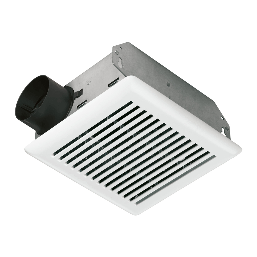
- Rough Opening: 8 1⁄4 " long by 71⁄4 " wide
- Housing Size: 73⁄16" x 81⁄16" x 37⁄8"
![warning]() NOTE: Refer to Figure 1A.
NOTE: Refer to Figure 1A.
Remove motor plate from housing before mounting. Insert screwdriver between motor plate and side of housing with duct collar. Gently pry the housing away from the motor plate while pulling up on the motor plate to disengage the plate from the housing.
- With nails or screws, secure (but do not tighten) the housing to theceiling or wall through the two (2) keyhole slots in the mounting tabs.
![warning]() NOTE: Prior to completely tightening, adjust the housing so that the outer edge will remain 1⁄8" to 1⁄4" recessed from the finished ceiling or wall. For the grille to fit properly, the housing must not extend outside the finished wall surface.
NOTE: Prior to completely tightening, adjust the housing so that the outer edge will remain 1⁄8" to 1⁄4" recessed from the finished ceiling or wall. For the grille to fit properly, the housing must not extend outside the finished wall surface. - Secure discharge adapter over flanges on housing and connectducting to discharge. Make sure housing is securely mounted to prevent fan from vibrating and causing noise.


Be certain all wiring complies with local codes and the unit is properly grounded.
- Refer to Figure 2.
Run power leads from the wall or timer switch to the unit. - Using approved wire connectors, connect supply wires to fan wires: black to black and white to white. Connect ground wire (green or bare) to the green ground screw or ground wire in the fan's junction box.
DUCTING

- Refer to Figures 3 and 4. Run 3" round duct from the discharge opening to the outside of the home. prevent fan from vibrating and causing noise.
INSTALLING THE FAN AND GRILLE

- Refer to Figure 5. Snap scroll band (provided with 70 CFM model only) into housing.
- Refer to Figure 1. Insert the two tabs on the motor plate into slots in housing.
- Push the motor plate into the housing until the plate snaps firmly in place. Make sure the blower wheel turns freely.
- Insert the motor plug into the housing's receptacle.
- To install the grille, compress the spring clips and insert in the slots on either side of the motor plate. Push the grille up into place on the ceiling.
Limited Warranty
Warranty Period and Exclusions: Broan-NuTone LLC (the "Company") warrants to the original consumer purchaser of its product ("you") that the product (the "Product") will be free from material defects in the Product or its workmanship for a period of one (1) year from the date of original purchase. The warranty on the light bulbs provided with the Product is one (1) year and does not cover lamp/bulb breakage.
The limited warranty period for any replacement parts provided by the Company and for any Products repaired or replaced under this limited warranty shall be the remainder of the original warranty period.
This warranty does not cover speed controls, fluorescent lamp starters, tubes, halogen and incandescent bulbs, fuses, filters, ducts, roof caps, wall caps and other accessories for ducting that may be purchased separately and installed with the Product.
How to Obtain Warranty Service: To qualify for warranty service, you must
- notify the Company at the address or telephone number stated below within seven (7) days of discovering the covered defect,
- give the model number and part identification and
- describe the nature of any defect in the Product or part.
At the time of requesting warranty service, you must present evidence of the original purchase date. If you cannot provide a copy of the original written limited warranty, then the terms of the Company's most current written limited warranty for your particular product will control. The most current limited written warranties for the Company's products can be found at www.nutone.com
Broan-NuTone LLC
926 West State Street, Hartford, WI 53027
www.nutone.com;
800-637-1453

Documents / Resources
References
Download manual
Here you can download full pdf version of manual, it may contain additional safety instructions, warranty information, FCC rules, etc.
Download NuTone 695, 696N - Bathroom Exhaust Blower Fan Installation Manual
Advertisement


Need help?
Do you have a question about the 695 and is the answer not in the manual?
Questions and answers