Apollo 55000-852 - Sounder Control Unit Installation Guide
- Installation manual (2 pages)
Advertisement
General
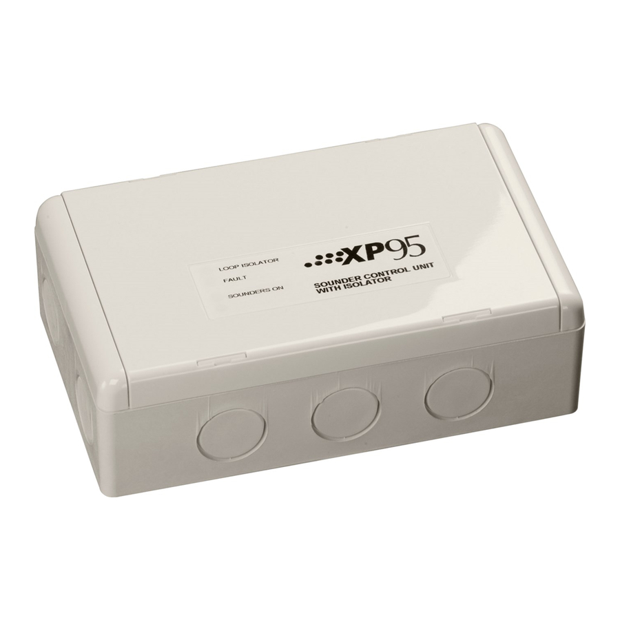
The Sounder Control Unit, part no 55000-852, is designed to control a zone of sounders powered by an external DC supply. It is supplied with a backbox for surface mounting and has an integral isolator as standard.
Note: The Sounder Control Unit is not designed for outdoor use unless it is mounted in a suitable weatherproof enclosure.
Installation
- Mount the backbox as required and install all cables for termination. Ensure that earth continuity is maintained.
- Remove the cover plate (if secured) from the Sounder Control Unit assembly by inserting the blade of a terminal screwdriver into each of the four securing clips in turn, gently prising the outer edge of the cover plate over the clips underneath. DO NOT USE EXCESSIVE FORCE.
- Terminate all cables observing polarity.
Note: Cable length to be kept 3m or under. - Gently push the completed assembly towards the backbox until the mounting holes are aligned and secure with the two mounting screws provided. DO NOT OVERTIGHTEN.
- Set the address of the unit as shown.
- Finally, when commissioning is complete, fi t the cover plate by placing it in position, observing the correct orientation (LEDs on the PCB must be aligned with viewing holes). Apply pressure to the cover plate until all four clips are holding it in position.
Wiring Details
All wiring terminals accept solid or stranded cables up to 2.5mm².

(Note: Polarity must be observed)
Fuse: 1.0A, anti-surge
Local supply: 24V (9—32V )
Sounder zone end-of-line resistor: 10K 1/3Watt
Current consumption at 28V (no protocol)
switch-on surge, max 120ms 4.0mA
quiescent 1.5mA
sounders operated 1.7mA
fault 3.6mA
LED Indicators
Three LEDs are fi tted to the PCB to indicate functions as follows:
 Isolator Isolator | Illuminated yellow when a short circuit on the loop causes the integral isolator to operate |
| Sounders On | Illuminated red when sounder relay is energised |
| Fault | Illuminated yellow under any fault condition (except group address conflict) |
Address Setting
The Sounder Control Unit is designed to be polled by the control panel in two ways, individually or as part of a group. Two DIL switches are provided for setting the addresses.
Note: one switch is sealed with a sticky label. This label should not be removed unless the unit is to be controlled as part of a group.
Individual Address Setting
The individual address of the Sounder Control Unit is set using the seven-segment DIL switch. Each segment of the switch must be set to "0" or "1", using a small screwdriver or similar tool. A complete list of address settings is shown opposite.

Group Address Setting
In Group mode the Sounder Control Unit responds to an additional address referred to as the "group address", which is used to activate groups of Sounder Control Units simultaneously. (The unit continues to respond to its own individual address and report its status from that address in the normal way.) The group address is selected by the four-segment DIL switch which is factoryset to 0000. A group address may be any spare address within–and only within–the range 112 to 126 inclusive. The required group address is set by moving one or more of the segments on the switch to "1". The following table shows the settings for the group address switch.

Commissioning
It is important that the Sounder Control Unit be fully tested after installation. An XP95 Test Set, part no 55000-870, may be used to carry out functional testing of individual units. It can also be used to perform data integrity tests of an entire loop. For a full technical specifi cation of the Sounder Control Unit, please refer to the Sounder Control Unit PIN Sheet, PP2094. For further information on isolators, please refer to PP2090.
The cause and effect programming (the control panel software responsible for switching sounders and outputs etc. in alarm condition) should be fully checked, along with all equipment connected to the Sounder Control Unit.
Note: If this product has been subjected to excessive shock during transportation, it may be received with the relay contacts in the 'set' position. Reset the relay by subjecting it to one operating cycle before commissioning the system.
Functional Test Data

*Note: group mode is disabled if the group address DIL switch is set to '0000', irrespective of the protocol message
Troubleshooting
Before investigating individual units for faults, it is very important to check that the system wiring is fault free. Earth faults on a data loop or any ancillary zone wiring may cause communication errors. Many fault conditions are the result of simple wiring errors. Check all connections to the unit and make sure the correct value resistors are fi tted where necessary.
Fault Finding
| Problem | Possible Cause |
| No response or missing | Incorrect individual address setting Incorrect loop wiring |
| Fault condition reported | Incorrect group or individual address setting Incorrect wiring of sounder zone or fault input Faulty sounder Local supply faulty or polarity incorrect Fuse blown on sounder PCB |
| Sounders do not operate | Incorrect wiring Incorrect group address setting Fuse blown on sounder PCB Incorrect cause and effect programming Faulty sounder Panel fault |
| Sounders operate continuously | Incorrect sounder zone wiring |
| Analogue value unstable | Dual address Loop data fault, data corruption |
©Apollo Fire Detectors Limited 2011
Apollo Fire Detectors Limited, 36 Brookside Road, Havant, Hants, PO9 1JR, UK
Tel +44 (0)23 9249 2412
Fax +44 (0)23 9249 2754
Email: techsales@apollo-fi re.co.uk
Website: www.apollo-fire.co.uk

Documents / ResourcesDownload manual
Here you can download full pdf version of manual, it may contain additional safety instructions, warranty information, FCC rules, etc.
Download Apollo 55000-852 - Sounder Control Unit Installation Guide
Advertisement


Need help?
Do you have a question about the 55000-852 and is the answer not in the manual?
Questions and answers