Advertisement
Quick Links
The cause and effect programming (the control panel software responsible for switching
sounders and outputs etc. in alarm condition) should be fully checked, along with all
equipment connected to the Sounder Control Unit.
Note: If this product has been subjected to excessive shock during transportation, it may be
received with the relay contacts in the 'set' position. Reset the relay by subjecting it to one
operating cycle before commissioning the system.
Functional Test Data
output bit
function
2
group mode*
1 = off
0 = on
1
pulsed mode
1 = on
0 = off
0
continuous mode
1 = on
0 = off
*Note: group mode is disabled if the group address DIL switch is set to '0000', irrespective of the
protocol message
Troubleshooting
Before investigating individual units for faults, it is very important to check that the system wiring
is fault free. Earth faults on a data loop or any ancillary zone wiring may cause communication
errors. Many fault conditions are the result of simple wiring errors. Check all connections to the
unit and make sure the correct value resistors are fi tted where necessary.
Fault Finding
Problem
No response or missing
Fault condition reported
Sounders do not operate
Sounders operate continuously
Analogue value unstable
©Apollo Fire Detectors Limited 2011
Apollo Fire Detectors Limited, 36 Brookside Road, Havant, Hants, PO9 1JR, UK
Tel +44 (0)23 9249 2412 Fax +44 (0)23 9249 2754
Email: techsales@apollo-fi re.co.uk Website: www.apollo-fi re.co.uk
input bit
function
2
group mode
1 = group
0 = individual
1
pulsed mode confi rmed
1 = on
0 = off
0
continuous mode confi rmed
1 = on
0 = off
Possible Cause
Incorrect individual address setting
Incorrect loop wiring
Incorrect group or individual address setting
Incorrect wiring of sounder zone or fault input
Faulty sounder
Local supply faulty or polarity incorrect
Fuse blown on sounder PCB
Incorrect wiring
Incorrect group address setting
Fuse blown on sounder PCB
Incorrect cause and effect programming
Faulty sounder
Panel fault
Incorrect sounder zone wiring
Dual address
Loop data fault, data corruption
4
39214-129/2011/Issue 3
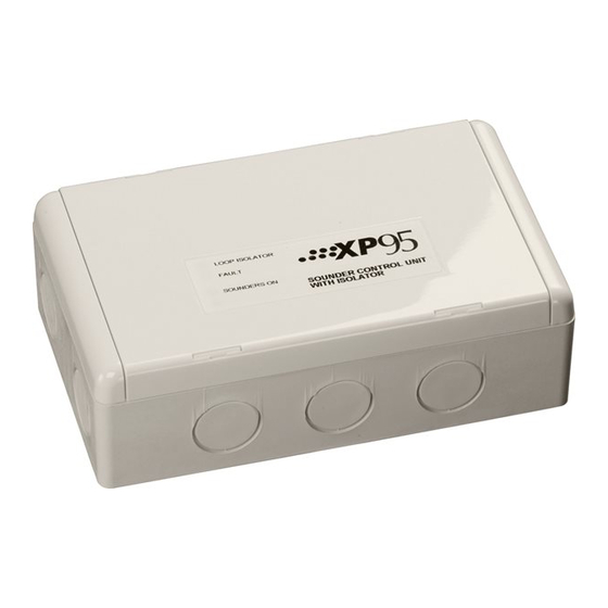
General
The Sounder Control Unit, part no 55000-852, is designed to control a zone of sounders
powered by an external DC supply. It is supplied with a backbox for surface mounting and has
an integral isolator as standard.
Note: The Sounder Control Unit is not designed for outdoor use unless it is mounted in a suitable
weatherproof enclosure.
Installation
1.
Mount the backbox as required and install all cables for termination. Ensure that earth
continuity is maintained.
2.
Remove the cover plate (if secured) from the Sounder Control Unit assembly by inserting
the blade of a terminal screwdriver into each of the four securing clips in turn, gently
prising the outer edge of the cover plate over the clips underneath. DO NOT USE EXCESSIVE
FORCE.
3.
Terminate all cables observing polarity.
Note: Cable length to be kept 3m or under.
4.
Gently push the completed assembly towards the backbox until the mounting holes are
aligned and secure with the two mounting screws provided. DO NOT OVERTIGHTEN.
5.
Set the address of the unit as shown on page 3.
6.
Finally, when commissioning is complete, fi t the cover plate by placing it in position,
observing the correct orientation (LEDs on the PCB must be aligned with viewing holes).
Apply pressure to the cover plate until all four clips are holding it in position.
Sounder Control Unit
Installation Guide
1
Advertisement

Related Manuals for Apollo 55000-852


Summary of Contents for Apollo 55000-852
- Page 1 fi tted where necessary. The Sounder Control Unit, part no 55000-852, is designed to control a zone of sounders powered by an external DC supply. It is supplied with a backbox for surface mounting and has Fault Finding an integral isolator as standard.
- Page 2 Wiring Details DIL switch DIL switch DIL switch DIL switch DIL switch All wiring terminals accept solid or stranded cables up to 2.5mm². setting setting setting setting setting addr 1234567 addr 1234567 addr 1234567 addr 1234567 addr 1234567 1000000 1101000 1010100 1111100 1001010...
Need help?
Do you have a question about the 55000-852 and is the answer not in the manual?
Questions and answers