
Related Manuals for Woodley CLINISPIN HORIZON 842VES


Summary of Contents for Woodley CLINISPIN HORIZON 842VES
- Page 1 7711038 Operator’s Manual clinispin hOrizOn 842VEs Laboratory Centrifuge Rev. A...
-
Page 2: Table Of Contents
TablE Of cOnTEnTs Model Description page 3 Supplied Equipment page 3 Warranty Information page 3 Specifications page 4 Control Panel / Parts of the Centrifuge page 5 Setup Location page 6 Initial Setup Procedure pages 6,7 Operation page 7 Rotor Configurations Performance Plus Horizontal Rotor page 7 6-Place Horizontal Rotor... -
Page 3: Model Description
7786017 Also included (not shown): • One (1) Mains Lead • One (1) Operator’s Manual WARRANTY: Woodley Equipment Company warranties that this centrifuge is free from defects in workmanship and parts for 2 years. Made in the USA Old Station Park Buildings St. John’s Street, Horwich Bolton BL6 7NY, United Kingdom Tel: +44 (0) 1204 669033 •... -
Page 4: Specifications
Specifications: General Specifications for the Horizon Model 842VES Centrifuge Overall Dimensions (h x W x D): 8.0 in. x 11.0 in. x 13.5 in. centrifuge Motor: 1/2 H.P. Brushless DC protection breaker: 4 Amp. re–settable Timer: electronic, with hold or 0 to 99 minutes, +/- 1% Weight: 23 lbs. -
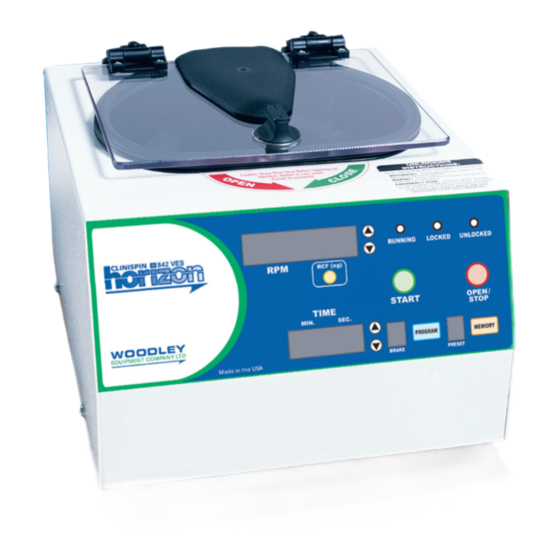
Page 5: Control Panel / Parts Of The Centrifuge
cOnTrOl panEl / parTs Of ThE cEnTrifuGE: lid Knob lid safety interlock system control panel (see below) cabinet up/Down rpM locked running unlocked change buttons indicator indicator indicator light light light rpM Display rcf conversion button start button Open / stop button Time Display up/Down Time program... -
Page 6: Setup Location
If any problems are found during the initial setup procedure, refer to the troubleshooting section. For further assistance, contact Woodley Equipment Company LTD. at +44 (0) 1204 669033 Plug the female end of the mains Lead into the rear of the centrifuge. Plug the male end into an approved electrical outlet. -
Page 7: Operation
OpEraTiOn: nOTE: follow the initial setup procedure before initial operation. 1. Press the ‘OPEN / STOP’ button to unlock the lid and then open the lid. Insert cushions (if needed) into the tube carriers (holders) for the tube size you are using. Refer to ‘Rotor Configurations’ for assistance. Place the test tube samples into the tube carriers (holders). Be sure to follow the rules for balanced loads. -
Page 8: 6-Place Horizontal Rotor
Tube Holder Configurations: The horizontal rotor is capable of spinning test tubes up to 17 mm x 100 mm with its horizontal rotor. Use the following chart and drawing to determine which tube holder and cushion combination should be used with your application. DIRECTIONS: Compare the tube to be spun with the three boxes shown below. -
Page 9: 6-Place Fixed Angle Rotor
Tube Holder Configurations: The fixed angle rotor is capable of spinning test tubes up to 17 mm x 125 mm. Use the following chart and drawing to determine which tube holder and cushion combination should be used with your application. DIRECTIONS: Compare the tube to be spun with the three boxes shown below. 2. Find the box that most closely matches the tube’s length. NOTE: The tube length with its stopper or cap must be shorter then the chosen box or the tube will not fit properly in the tube holder. -
Page 10: Control Panel Functions
cOnTrOl panEl funcTiOns: Time Adjustment and Timer Operation - The run time may be set from 30 seconds to 99 minutes and 30 seconds. Press the up and down arrow buttons next to the time display to adjust the run time. Adjustments may be made prior to a run or after a run begins. A quick tap will adjust the time by 30 seconds. -
Page 11: Braking Rate
aDVancED usEr sETTinGs (continued): Braking Rate - The user may adjust the braking rate from minimum ( slowest deceleration, 0) to maximum (quickest deceleration, 9) using the following procedure: While the centrifuge is idle, press the PROGRAM button. Use the UP/DOWN arrow buttons next to the speed display until “BRAKE” is displayed in the speed display. The current braking rate is displayed in the brake display. -
Page 12: Memory Locations / Storing And Recalling
MEMOry lOcaTiOns / sTOrinG anD rEcallinG: The Clinispin horizon 842VES centrifuge is capable of storing up to 10 user-defined presets. These memory presets contain all of the settings needed to define a specific run, (run time, speed, acceleration rate, braking rate, etc.). The user can use these memory locations to quickly configure the centrifuge for a specific test type and ensure that the test is run in the same way each time by recalling this same setting. Store a configuration in a memory location Adjust the various settings (speed, time, acceleration rate, etc.) for the configuration to be saved. Press and hold the PROGRAM button until the preset display begins to flash. Press the MEMORY button to increment the memory location by one. Continue to press the memory button until the desired location is displayed. -
Page 13: Care And Preventative Maintenance
carE anD prEVEnTaTiVE MainTEnancE: With proper care and maintenance your Horizon centrifuge will provide years of laboratory service. For proper care, the following steps should be taken: 1. provide adequate Ventilation: For cooling purposes, the Horizon draws in ambient air through the air intake cover on the top of the lid and exhausts this air in the rear of the base. -
Page 14: Rotor Removal And Installation
rOTOr rEMOVal anD insTallaTiOn: To remove the rotor: 1. Unlock the centrifuge by pushing the ‘OPEN / EMERGENCY STOP’ button and unlock and open the lid. CAUTION: Unplug the centrifuge from the electrical outlet at this time to eliminate the possibility of electrical shock or other injury. Remove the test tube holders. Remove the screw in the center of the rotor with a 1/8” hex key by turning the screw counter clockwise. -
Page 15: Troubleshooting
• If the red ‘UNLOCKED’ indicator will not illuminate or the locking mechanism will not disengage, the electronics or locking mechanism may be damaged. Have a technician service the centrifuge or contact Woodley Equipment Company for further assistance. For additional assistance, services and technical support contact Woodley Equipment Company LTD. -
Page 16: Safety
The Clinispin Horizon 842VES complies with all requirements of CE EN 61000-3-2, -3-3, EN 61000-4-2, -4-3, -4-4, -4-5, -4-6, -4-11, EN 61010-1, -2-020 and UL standard 3101–2– 20, Can/CSA C22.2 No. 1010.1 , Can/CSA C22.2 No. 1010.2.20 safETy: horizon lid safety switch: The Horizon lid is secured to the top of the cabinet by a locking knob and pawl system. -
Page 17: Replacement Parts
Contact your authorized dealer or Drucker Diagnostics to order replacement parts or accessories. replacement parts: 12-Place (75mm part no. Description only) 7724177 Rubber Foot Fixed-angle Stat rotor 7751068 Lid Tray Micro-Switch p/n 7786001 7723002 Lid Tray Solenoid 7735011 Motor, ½ H.P. Brushless DC 12-Place combo 7717041 PC Control Board...
Need help?
Do you have a question about the CLINISPIN HORIZON 842VES and is the answer not in the manual?
Questions and answers