Page 1
Form No. 3425-565 Rev A TimeCutter ® ZS 4200T or ZS 5000 Riding Mower Model No. 74686—Serial No. 400000000 and Up Model No. 74688—Serial No. 400000000 and Up *3425-565* A Register at www.Toro.com. Original Instructions (EN)
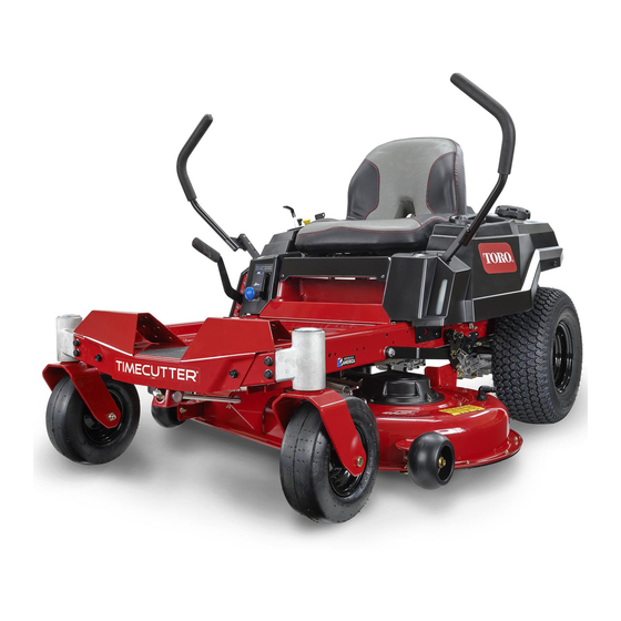
Page 2
Whenever you need service, genuine Toro parts, or Important: If you are using a machine with a Toro additional information, contact an Authorized Service engine above 1500 m (5,000 ft) for a continuous Dealer or Toro Customer Service and have the model period, ensure that the High Altitude Kit has been and serial numbers of your product ready.
Contents This manual uses 2 words to highlight information. Important calls attention to special mechanical information and Note emphasizes general information Safety ............... 4 worthy of special attention. Safety Alert Symbol ..........4 General Safety ........... 5 Slope Indicator ........... 6 Safety and Instructional Decals ......
Safety Checking the Tire Pressure....... 48 Releasing the Electric Brake ......49 Belt Maintenance ..........49 This machine has been designed in accordance with Inspecting the Belts .......... 49 EN ISO 5395:2013. Replacing the Mower-Deck Belt......49 Mower Maintenance..........51 Blade Safety .............
General Safety This machine is capable of amputating hands and feet and of throwing objects. Toro designed and tested this lawn mower to offer reasonably safe service; however, failure to comply with safety instructions may result in injury or death.
Slope Indicator g011841 Figure 4 You may copy this page for personal use. 1. The maximum slope you can operate the machine on is 15 degrees. Use the slope chart to determine the degree of slope of hills before operating. Do not operate this machine on a slope greater than 15 degrees. Fold along the appropriate line to match the recommended slope.
Safety and Instructional Decals Safety decals and instructions are easily visible to the operator and are located near any area of potential danger. Replace any decal that is damaged or missing. decalbatterysymbols Battery Symbols Some or all of these symbols are on your battery. 1.
Page 8
decal106-8717 106-8717 decal119-8815 1. Read the instructions before servicing or performing 119-8815 maintenance. 1. Parking position 4. Neutral 2. Check tire pressure every 25 operating hours. 2. Fast 5. Reverse 3. Grease every 25 operating hours. 3. Slow 4. Engine decal112-9840 112-9840 For Models with 127 cm (50 inch) Decks...
Page 9
decal120-5470 120-5470 For Models with 127 cm (50 inch) Decks 1. Height of cut...
Page 10
decal121-0772 121-0772 For Models with 107 cm (42 inch) Decks 1. Fast 4. Choke 2. Continuous-variable setting 5. Power takeoff (PTO), blade-control switch 3. Slow...
Page 11
decal121-0773 121-0773 For Models with 127 cm (50 inch) Decks 1. Fast 4. Choke 2. Continuous-variable setting 5. Power takeoff (PTO), blade-control switch 3. Slow...
Page 12
decal121-2989b 121-2989 1. Bypass lever position for 2. Bypass lever position for pushing the machine operating the machine decal131-1097 131-1097 1. Oil drain 131-3948 decal131-3948 131-3948 1. Slow 3. Fast 2. Towing...
Page 13
decal132-0869 132-0869 Note: This machine complies with the industry standard stability test in the static lateral and longitudinal tests with the maximum recommended slope indicated on the decal. Review the instructions for operating the machine on slopes in the Operator’s Manual as well as the conditions in which you would operate the machine to determine whether you can operate the machine in those conditions on that day and at that site.
Page 14
decal132-0872 132-0872 1. Thrown object 3. Severing hazard of hand hazard—keep bystanders or foot—keep away from away from the machine. moving parts. 2. Thrown object hazard, 4. Entanglement raised baffle—do not hazard—keep away operate the machine with from moving parts; keep an open deck;...
Product Overview g027829 Figure 5 1. Height-of-cut lever 5. Mower deck 9. Fuel-tank cap 13. Rear drive wheel 2. Motion-control levers 6. Anti-scalp roller 10. Engine 14. Engine guard 7. Front caster wheels 3. Operator seat 11. Control panel 4. Smart Speed™ lever 8.
Page 16
Contact Smart Speed™ Control System your Authorized Service Dealer or authorized Toro Lever distributor or go to www.Toro.com for a list of all approved attachments and accessories. The Smart Speed™ Control-System lever, located To ensure optimum performance and continued safety...
Only use accessories and Refer to the Maintenance section and perform all the attachments approved by Toro. necessary inspection and maintenance steps. • Inspect the area where the equipment is to be used and remove all rocks, toys, sticks, wires, bones, and other foreign objects.
Fuel Safety DANGER In certain conditions during fueling, static Use extreme care when handling fuel. electricity can be released causing a spark which can ignite gasoline vapors. A fire or DANGER explosion from gasoline can burn you and In certain conditions gasoline is extremely others and cause property damage.
Adding Fuel Note: Do not fill the fuel tank completely full. The empty space in the tank allows the fuel to expand. Recommended Fuel • For best results, use only clean, fresh (less than 30 days old), unleaded gasoline with an octane rating of 87 or higher ((R+M)/2 rating method).
Using the Safety-Interlock motion-control levers to the center, unlocked position, engage the blade-control switch, and System rise slightly from the seat; the engine should shut off. WARNING Positioning the Seat If the safety-interlock switches are disconnected or damaged, the machine could The seat can move forward and backward.
Adjusting the Converting to Side Motion-Control Levers Discharge Adjusting the Height Machines with 107 cm (42-inch) Mower Decks You can adjust the motion-control levers higher or lower for maximum comfort (Figure 10). The mower deck and mower blades shipped with the machine were designed for optimum mulching and side-discharge performance.
Page 22
g230249 Figure 14 g230250 Figure 12 On the top of the discharge cover, engage the 1. Discharge cover 3. Bracket on the mower hook-shaped latch around the pivot rod of the deck deflector assembly (Figure 15). 2. Metal tab Installing the Discharge Cover for Mulching Park the machine on a level surface, disengage the blade-control switch, and engage the parking brake.
Page 23
Removing the Right Baffle for Side-Discharging Park the machine on a level surface, disengage the blade-control switch, and engage the parking brake. Shut off the engine, remove the key, and wait for all moving parts to stop before leaving the operating position.
During Operation During Operation Safety General Safety The operator must use their full attention when operating the machine. Do Not engage in any activity that causes distractions; otherwise, injury or property damage may occur. g015321 Figure 18 WARNING 1. Bolt (5/16 x 3/4 inch) 3.
Page 25
• Be sure all drives are in neutral and parking brake – Whenever you leave the mower. Do Not leave is engaged before starting engine. a running machine unattended. • Start the engine carefully according to instructions • Stop engine, wait for all moving parts to stop: with feet well away from the blades.
Operating the Mower distance (twice the width of the machine) between the machine and any hazard. Use a walk behind Blade-Control Switch (PTO) machine or a hand trimmer to mow the grass in these areas. The blade-control switch (PTO) starts and stops the mower blades and any powered attachments.
Operating the Throttle Operating the Choke You can move the throttle control between F Use the choke to start a cold engine. positions (Figure 23). Pull up the choke knob to engage the choke before using the key switch (Figure 24).
Starting the Engine CAUTION Children or bystanders may be injured if they Note: A warm or hot engine may not require choking. move or attempt to operate the machine while Important: Do not engage the starter for more it is unattended. than 5 seconds at a time.
Page 29
performance. Always operate in the full throttle position when mowing. WARNING The machine can spin very rapidly. You may lose control of the machine and cause personal injury or damage to the machine. • Use caution when making turns. • Slow the machine down before making sharp turns.
Using the Side Discharge Suggested Trim uses: The mower has a hinged grass deflector that Parking disperses clippings to the side and down toward the Heavy, wet turf. grass Training DANGER Trimming Without a grass deflector, discharge cover, or grass a complete grass-catcher assembly mounted Bagging in place, you and others are exposed to blade...
Adjusting the Height of Cut Adjusting the Anti-Scalp Rollers Note: The transport position is the highest height-of-cut position or cutting height at 115 mm (4-1/2 inches) as shown in Figure Adjusting the Anti-Scalp Rollers Height of cut is controlled by the lever located to the Machines with 107 cm (42-inch) Mower Decks right of the operating position (Figure...
Operating Tips Park the machine on a level surface, disengage the blade-control switch and engage the parking brake. Using the Fast Throttle Setting Shut off the engine, remove the key, and wait For best mowing and maximum air circulation, operate for all moving parts to stop before leaving the the engine at the F position.
Tighten sharpen the blades as necessary. If a blade is loose hardware. damaged or worn, replace it immediately with a genuine Toro replacement blade. Transporting Transporting the Machine Use a heavy-duty trailer or truck to transport the machine.
Page 34
on the down side of the slope and the ramp extends up the slope. This will minimize the ramp angle. WARNING Loading a machine onto a trailer or truck increases the possibility of tip-over and could cause serious injury or death. •...
Page 35
and loss of control. Reduce the towed weight and slow down. • Stopping distance increases with the weight of the towed load. Travel slowly and allow extra distance to stop. • Make wide turns to keep the attachment clear of the machine.
Pushing the Machine by brake manually if necessary; refer to Releasing the Electric Brake (page 49). Hand Operating the Machine Important: Always push the machine by hand. Do not tow the machine, because towing may Move the bypass levers rearward through the keyhole damage it.
Maintenance Note: Determine the left and right sides of the machine from the normal operating position. Recommended Maintenance Schedule(s) Maintenance Service Maintenance Procedure Interval • Change the engine oil and filter. After the first 5 hours • Check the safety-interlock system. •...
Page 38
Removal or modification of original equipment, parts and/or accessories may alter the warranty, controllability, and safety of the machine. Unauthorized modifications to the original equipment or failure to use original Toro parts could lead to serious injury or death. Unauthorized changes to the machine, engine, fuel or venting system, may violate applicable safety standards such as: ANSI, OSHA and NFPA and/or government regulations such as EPA and CARB.
Pre-Maintenance Lubrication Procedures Greasing the Bearings Raising the Seat Service Interval: Every 25 hours—Grease all the lubrication points. Ensure that the parking brake is engaged. Lift the Grease Type: No. 2 lithium grease seat forward. Park the machine on a level surface, disengage You can access following components by raising the the blade-control switch, and engage the parking seat:...
Engine Maintenance Engine Safety • Shut off the engine before checking the oil or adding oil to the crankcase. • Keep your hands, feet, face, clothing, and other body parts away the muffler and other hot surfaces. g027800 Servicing the Air Cleaner Service Interval: Before each use or daily Note: Service the air cleaner more frequently (every...
Page 41
Servicing the Foam Air-Cleaner Installing the Air Cleaner Element Install the foam element over the paper element. Service Interval: Every 25 hours/Monthly (whichever Note: Ensure that you do not damage the comes first)—Clean the air-cleaner elements. foam element (more often in dusty, Align the holes of the filter into the manifold dirty conditions).
Servicing the Engine Oil Engine-Oil Specifications Oil Type: Detergent oil (API service SF, SG, SH, SJ, or SL) Crankcase Capacity: 2.4 L (81 fl oz) with oil filter Viscosity: See the table below. g029683 Figure 43 Checking the Engine-Oil Level Service Interval: Before each use or daily Note: Check the oil when the engine is cold.
Page 43
Change the engine-oil filter (Figure 46). Note: Ensure that the oil-filter gasket touches the engine and then turn the filter an extra 3/4 turn. g027799 g027477 Figure 46 Slowly pour approximately 80% of the specified oil into the filler tube and slowly add the additional oil to bring it to the Full mark (Figure 47).
g027478 Figure 48 Checking the Spark Plug Important: Do not clean the spark plug(s). Always replace the spark plug(s) when it has a black coating, worn electrodes, an oily film, or cracks. If you see light brown or gray on the insulator, the engine is operating properly.
Cleaning the Cooling Fuel System System Maintenance Park the machine on a level surface, disengage the blade-control switch (PTO), and engage the DANGER parking brake. In certain conditions, fuel is extremely Shut off the engine, remove the key, and wait flammable and highly explosive.
Electrical System Maintenance Electrical System Safety • Disconnect the battery before repairing the g027939 machine. Disconnect the negative terminal first and the positive last. Connect the positive terminal first and the negative last. • Charge the battery in an open, well-ventilated area, away from sparks and flames.
Page 47
Charge the battery for a minimum of 1 hour at WARNING 6 to 10 A. Incorrectly removing the cables from Note: Do not overcharge the battery. battery could damage the machine and cables, causing sparks. Sparks can When the battery is fully charged, unplug cause the battery gasses to explode, the charger from the electrical outlet, then resulting in personal injury.
Servicing the Fuses Drive System Maintenance The electrical system is protected by fuses. It requires no maintenance; however, if a fuse blows, check the component/circuit for a malfunction or short. Checking the Tire Pressure Fuse type: • Main—F1 (30 A, blade-type) Service Interval: Every 25 hours—Check tire pressure.
Refer to Releasing the Mower-Deck Curtain (page 39). Using a spring-removal tool, (Toro Part No. 92-5771), remove the idler spring from the deck hook to remove tension on the idler pulley, and roll the belt off the pulleys...
Page 50
WARNING The spring is under tension when installed and can cause personal injury. Be careful when removing the belt. g014931 Figure 59 Mower Decks with 3 Blades 1. Idler pulley 4. Spring 2. Mower belt 5. Engine pulley 3. Outside pulley 6.
Mower Maintenance Blade Safety A worn or damaged blade can break, and a piece of the blade could be thrown toward you or bystanders, resulting in serious personal injury or death. Trying to repair a damaged blade may result in discontinued safety certification of the product.
Page 52
g014973 g014973 Figure 62 Figure 64 1. Blade (in position for measuring) 1. Opposite blade edge (in position for measuring) 2. Level surface 2. Level surface 3. Measured distance between blade and the surface (A) 3. Second measured distance between blade and surface (B) Rotate the same blade 180 degrees so that If the difference between A and B is greater the opposing cutting edge is now in the same...
Installing the Blades Install the blade onto the spindle shaft (Figure 65). Important: The curved part of the blade must be pointing upward toward the inside of the mower to ensure proper cutting. Install the curved washer (cupped side toward the blade) and the blade bolt (Figure 65).
Page 54
g009682 Figure 68 Mower Decks with 2 Blades g027588 1. Blades side to side 3. Outside cutting edges Figure 70 2. Sail area of the blade 4. Measure from the tip of the 1. Hanger bracket 3. Rear nut blade to the flat surface here.
g009658 Figure 71 Mower Decks with 2 Blades 1. Blades front to rear 2. Measure from the tip of the blade to the flat surface here. g014634 Figure 73 1. Adjusting rod 3. Locknut 2. Adjusting block To raise the front of the mower, tighten the adjustment nut.
Slide the mower deck out from underneath the machine. Note: Retain all parts for future installation. Installing the Mower Deck Park the machine on a level surface, disengage the blade-control switch (PTO), and engage the parking brake. Shut off the engine, remove the key, and wait for all moving parts to stop before leaving the operating position.
Cleaning Washing the Underside of the Mower Deck Service Interval: After each use—Clean the mower-deck housing. Important: You can wash the machine with a mild detergent and water. Do not pressure wash the machine. Avoid excessive use of water, especially near the control panel, under the seat, around the engine, hydraulic pumps, and motors.
Storage Turn the water off and remove the coupling from the washout fitting. Note: If the mower is not clean after 1 washing, Storage Safety soak it and let it stand for 30 minutes. Then repeat the process. • Let the engine cool before storing the machine. •...
Storing the Battery an alcohol-based stabilizer (ethanol or methanol). Fully charge the battery. Note: A fuel stabilizer/conditioner is most Let the battery rest for 24 hours, then check the effective when mixed with fresh fuel and battery voltage. used at all times. Note: If the battery voltage is below 12.6 V, Run the engine to distribute conditioned fuel...
Troubleshooting Problem Possible Cause Corrective Action The fuel tank is showing signs of collapsing 1. The air-cleaner paper element clogged. 1. Clean the paper element. or the machine is frequently showing signs of running out of fuel. The engine overheats. 1.
Page 61
Problem Possible Cause Corrective Action The machine does not drive. 1. The bypass valves are open. 1. Close the tow valves. 2. The traction belts are worn, loose, or 2. Contact an Authorized Service Dealer. broken. 3. The traction belts are off the pulleys. 3.
Page 64
The Toro Company (“Toro”) respects your privacy. When you purchase our products, we may collect certain personal information about you, either directly from you or through your local Toro company or dealer. Toro uses this information to fulfil contractual obligations - such as to register your warranty, process your warranty claim or to contact you in the event of a product recall - and for legitimate business purposes - such as to gauge customer satisfaction, improve our products or provide you with product information which may be of interest.
Need help?
Do you have a question about the 74686 and is the answer not in the manual?
Questions and answers