Table of Contents

Related Manuals for Toro 74682


Summary of Contents for Toro 74682
- Page 1 Form No. 3425-600 Rev A TimeCutter ® ZS 3200S or ZS 4200S Riding Mower Model No. 74682—Serial No. 400000000 and Up Model No. 74684—Serial No. 400000000 and Up *3425-600* A Register at www.Toro.com. Original Instructions (EN)
- Page 2 Whenever you need service, genuine Toro parts, or Important: If you are using a machine with a Toro additional information, contact an Authorized Service engine above 1500 m (5,000 ft) for a continuous Dealer or Toro Customer Service and have the model period, ensure that the High Altitude Kit has been and serial numbers of your product ready.
-
Page 3: Table Of Contents
Contents This manual uses 2 words to highlight information. Important calls attention to special mechanical information and Note emphasizes general information Safety ............... 4 worthy of special attention. Safety Alert Symbol ..........4 General Safety ........... 5 Slope Indicator ........... 6 Safety and Instructional Decals ...... -
Page 4: Safety
Safety Releasing the Electric Brake ......43 Belt Maintenance ..........43 Inspecting the Belts .......... 43 This machine has been designed in accordance with Replacing the Mower Belt ......... 43 EN ISO 5395:2013. Mower Maintenance..........45 Blade Safety ............. 45 Servicing the Cutting Blades ...... -
Page 5: General Safety
General Safety This machine is capable of amputating hands and feet and of throwing objects. Toro designed and tested this lawn mower to offer reasonably safe service; however, failure to comply with safety instructions may result in injury or death. -
Page 6: Slope Indicator
Slope Indicator g011841 Figure 4 You may copy this page for personal use. 1. The maximum slope you can operate the machine on is 15 degrees. Use the slope chart to determine the degree of slope of hills before operating. Do not operate this machine on a slope greater than 15 degrees. Fold along the appropriate line to match the recommended slope. -
Page 7: Safety And Instructional Decals
Safety and Instructional Decals Safety decals and instructions are easily visible to the operator and are located near any area of potential danger. Replace any decal that is damaged or missing. decalbatterysymbols Battery Symbols Some or all of these symbols are on your battery. 1. - Page 8 decal119-8815 119-8815 1. Parking position 4. Neutral 2. Fast 5. Reverse 3. Slow decal120-5469 120-5469 1. Height of cut decal121-0771 121-0771 1. Choke 4. S position 2. F position 5. Power takeoff (PTO), blade-control switch 3. Continuous-variable setting...
- Page 9 decal121-2989b 121-2989 1. Bypass lever position for 2. Bypass lever position for pushing the machine operating the machine 131-3948 decal131-3948 131-3948 1. Slow 3. Fast 2. Towing...
- Page 10 decal132-0869 132-0869 Note: This machine complies with the industry standard stability test in the static lateral and longitudinal tests with the maximum recommended slope indicated on the decal. Review the instructions for operating the machine on slopes in the Operator’s Manual as well as the conditions in which you would operate the machine to determine whether you can operate the machine in those conditions on that day and at that site.
- Page 11 decal132-0872 132-0872 1. Thrown object 3. Severing hazard of hand hazard—keep bystanders or foot—keep away from away from the machine. moving parts. 2. Thrown object hazard, 4. Entanglement raised baffle—do not hazard—keep away operate the machine with from moving parts; keep an open deck;...
-
Page 12: Product Overview
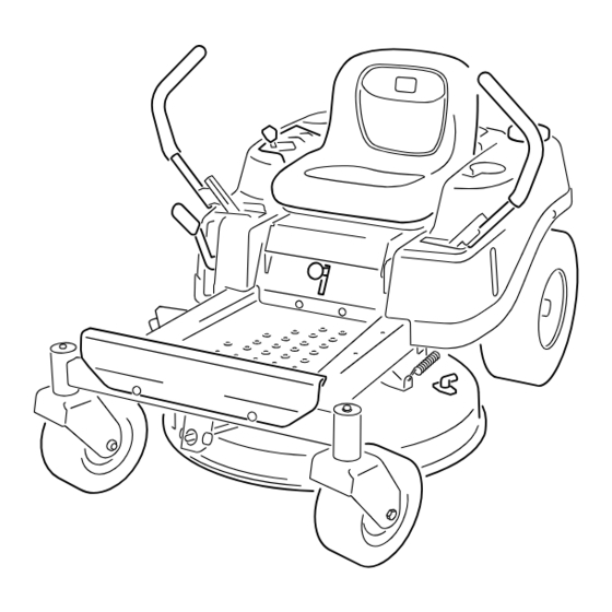
Product Overview g020240 Figure 5 1. Footrest 5. Control panel 9. Deflector 13. Front caster wheels 2. Height-of-cut lever 6. Operator seat 10. Engine 3. Motion-control lever 7. Rear drive wheel 11. Washout fitting 4. Smart Speed lever 8. Fuel-tank cap 12. - Page 13 Key Switch Park Position Move the motion-control levers outward from the The key switch, used to start and shut off the engine, has 3 positions: O , and S . Refer to center to the P position when exiting the machine TART Starting the Engine (page 24).
-
Page 14: Before Operation
Only use accessories and your Authorized Service Dealer or authorized Toro attachments approved by Toro. distributor or go to www.Toro.com for a list of all • approved attachments and accessories. Inspect the area where the equipment is to be... -
Page 15: Pre-Start
Pre-Start Fuel Safety Fill fuel tank on level ground. See Fuel Use extreme care when handling fuel. Recommendations in the Specifications section for additional gasoline information. DANGER Do Not add oil to gasoline. In certain conditions gasoline is extremely flammable and vapors are explosive. Do Not overfill fuel tank. -
Page 16: Adding Fuel
Adding Fuel DANGER In certain conditions during fueling, static Recommended Fuel electricity can be released causing a spark which can ignite gasoline vapors. A fire or • For best results, use only clean, fresh (less than explosion from gasoline can burn you and 30 days old), unleaded gasoline with an octane rating of 87 or higher ((R+M)/2 rating method). -
Page 17: Performing Daily Maintenance
Using the Safety-Interlock System WARNING If the safety-interlock switches are disconnected or damaged, the machine could operate unexpectedly, causing personal injury. • Do not tamper with the interlock switches. • Check the operation of the interlock switches daily and replace any damaged switches before operating the machine. -
Page 18: Positioning The Seat
Adjusting the rise slightly from the seat; the engine should shut off. Motion-Control Levers Positioning the Seat Adjusting the Height The seat can move forward and backward. Position You can adjust the motion-control levers higher or the seat where you have the best control of the lower for maximum comfort (Figure 10). -
Page 19: Converting To Side Discharge
Converting to Side Installing the Discharge Cover for Mulching Park the machine on a level surface, disengage Discharge the blade-control switch, and engage the parking brake. Machines with 81 cm (32-inch) Shut off the engine, remove the key, and wait for all moving parts to stop before leaving the Mower Decks operating position. - Page 20 Angle the metal tab on the discharge cover out of the slot in the bracket welded to the mower deck (Figure 13). g230249 Figure 15 On the top of the discharge cover, engage the hook-shaped latch around the pivot rod of the g230250 deflector assembly (Figure...
-
Page 21: During Operation
During Operation • Be sure all drives are in neutral and parking brake is engaged before starting engine. • Start the engine carefully according to instructions During Operation Safety with feet well away from the blades. • Never operate the mower with damaged guards, General Safety shields, or covers. - Page 22 – Whenever you leave the mower. Do Not leave distance (twice the width of the machine) between a running machine unattended. the machine and any hazard. Use a walk behind machine or a hand trimmer to mow the grass in •...
-
Page 23: Operating The Mower Blade-Control Switch (Pto)
Operating the Mower Operating the Throttle Blade-Control Switch (PTO) You can move the throttle control between F positions (Figure 21). The blade-control switch (PTO) starts and stops the Always use the F position when engaging the PTO. mower blades and any powered attachments. Engaging the Blade-Control Switch (PTO) g187361... -
Page 24: Starting The Engine
Starting the Engine Shutting Off the Engine Disengage the blades by moving the Important: Do not engage the starter for more blade-control switch to the O position (Figure than 5 seconds at a time. Engaging the starter 20). motor for more than 5 seconds can damage the starter motor. -
Page 25: Driving The Machine
Driving the Machine To go backward, slowly pull the motion-control levers rearward (Figure 25). The drive wheels turn independently, powered by hydraulic motors on each axle. You can turn 1 side in reverse while you turn the other forward, causing the machine to spin rather than turn. -
Page 26: Using The Side Discharge
Using the Side Discharge The following are only recommendations for use. Adjustments vary by grass type, moisture content, and the height of the grass. The mower has a hinged grass deflector that disperses clippings to the side and down toward the Suggested Trim turf. -
Page 27: Adjusting The Height Of Cut
Adjusting the Height of Cut Adjusting the Anti-Scalp Rollers Note: The transport position is the highest height-of-cut position or cutting height at 115 mm For Machines with 107 cm (4-1/2 inches) as shown in Figure (42-inch) Mower Decks Height of cut is controlled by the lever located to the right of the operating position (Figure 27). -
Page 28: Operating Tips
It is best to cut only about a third of the grass blade. genuine Toro replacement blade. Cutting more than that is not recommended unless grass is sparse, or it is late fall when grass grows more slowly. -
Page 29: After Operation
After Operation After Operation Safety General Safety • Park machine on level ground, disengage drives, set parking brake, stop engine, remove key or g027708 Figure 29 disconnect spark plug wire. Wait for all movement to stop and allow the machine to cool before 1. - Page 30 on the down side of the slope and the ramp extends up the slope. This will minimize the ramp angle. WARNING Loading a machine onto a trailer or truck increases the possibility of tip-over and could cause serious injury or death. •...
-
Page 31: Pushing The Machine By Hand
and loss of control. Reduce the towed weight and slow down. • Stopping distance increases with the weight of the towed load. Travel slowly and allow extra distance to stop. • Make wide turns to keep the attachment clear of the machine. -
Page 32: Maintenance
Maintenance Note: Determine the left and right sides of the machine from the normal operating position. Recommended Maintenance Schedule(s) Maintenance Service Maintenance Procedure Interval • Change the engine oil and filter. After the first 5 hours • Check the safety-interlock system. •... - Page 33 Removal or modification of original equipment, parts and/or accessories may alter the warranty, controllability, and safety of the machine. Unauthorized modifications to the original equipment or failure to use original Toro parts could lead to serious injury or death. Unauthorized changes to the machine, engine, fuel or venting system, may violate applicable safety standards such as: ANSI, OSHA and NFPA and/or government regulations such as EPA and CARB.
-
Page 34: Pre-Maintenance Procedures
Pre-Maintenance Lubrication Procedures Greasing the Bearings Raising the Seat Service Interval: Every 25 hours—Grease all the lubrication points. Ensure that the parking brake is engaged. Lift the Grease Type: No. 2 lithium grease seat forward. Park the machine on a level surface, disengage You can access following components by raising the the blade-control switch, and engage the parking seat:... -
Page 35: Engine Maintenance
Engine Maintenance Engine Safety • Shut off the engine before checking the oil or adding oil to the crankcase. • Keep your hands, feet, face, clothing, and other body parts away the muffler and other hot surfaces. Servicing the Air Cleaner Note: Service the air cleaner more frequently (every g233265... -
Page 36: Servicing The Engine Oil
Install the foam filter onto the paper filter (Figure 37). Install the foam and paper filter onto the air-cleaner housing. Install the air-cleaner cover, and tighten the 2 knobs (Figure 36). Servicing the Engine Oil Engine-Oil Specifications Oil Type: Detergent oil (API service SF, SG, SH, SJ, or higher) Crankcase Capacity: 1.4 L (47 fl oz) with oil filter Viscosity: See the table below. - Page 37 g027477 Figure 41 Slowly pour approximately 80% of the specified oil into the filler tube and slowly add the additional oil to bring it to the Full mark (Figure 42). g029369 Figure 40 Change the engine-oil filter (Figure 41). Note: Ensure the oil-filter gasket touches the engine, and then turn the filter an extra 3/4 turn.
-
Page 38: Servicing The Spark Plug
Servicing the Spark Plug Service Interval: Every 50 hours—Check the spark plug. Every 100 hours—Replace the spark plug. Ensure that the air gap between the center and side electrodes is correct before installing the spark plug. Use a spark plug wrench for removing and installing the spark plug and a gapping tool or feeler gauge to check and adjust the air gap. -
Page 39: Cleaning The Blower Housing
Fuel System Maintenance DANGER In certain conditions, fuel is extremely flammable and highly explosive. A fire or g206628 explosion from fuel can burn you and others Figure 44 and can damage property. Refer to Adding Fuel (page 16) for a complete list of fuel related precautions. -
Page 40: Electrical System Maintenance
Electrical System Maintenance Electrical System Safety • Disconnect the battery before repairing the g027506 machine. Disconnect the negative terminal first and the positive last. Connect the positive terminal first and the negative last. • Charge the battery in an open, well-ventilated area, away from sparks and flames. - Page 41 Charge the battery for a minimum of 1 hour at WARNING 6 to 10 A. Incorrectly removing the cables from Note: Do not overcharge the battery. battery could damage the machine and cables, causing sparks. Sparks can When the battery is fully charged, unplug cause the battery gasses to explode, the charger from the electrical outlet, then resulting in personal injury.
-
Page 42: Servicing The Fuses
Servicing the Fuses Drive System Maintenance The electrical system is protected by fuses. It requires no maintenance; however, if a fuse blows, check the component/circuit for a malfunction or short. Checking the Tire Pressure Fuse type: • Main—F1 (30 A, blade-type) Service Interval: Every 25 hours—Check tire pressure. -
Page 43: Releasing The Electric Brake
Refer to Releasing the Mower-Deck Curtain (page 34). Using a spring-removal tool (Toro Part No. 92-5771), remove the idler spring from the deck hook to remove tension on the idler pulley, and roll the belt off the pulleys... - Page 44 (Figure 53 Figure 54). g015129 Figure 53 Using a spring-removal tool (Toro Part No. Mower Decks with 1 Blade 92-5771), install the idler spring over the deck hook and place tension on the idler pulley and 1. Idler pulley 4. Spring...
-
Page 45: Mower Maintenance
Mower Maintenance Blade Safety A worn or damaged blade can break, and a piece of the blade could be thrown toward you or bystanders, resulting in serious personal injury or death. Trying to repair a damaged blade may result in discontinued safety certification of the product. - Page 46 For best performance and continued safety conformance of the machine, use genuine Toro replacement blades. Measure from the tip of the blade to the flat Replacement blades made by other manufacturers...
- Page 47 Check the balance of the blade by putting it on a blade balancer (Figure 63). Note: If the blade stays in a horizontal position, the blade is balanced and can be used. Note: If the blade is not balanced, file some metal off the end of the sail area only (Figure 62).
-
Page 48: Leveling The Mower Deck
Leveling the Mower Deck Check to ensure that the mower deck is level whenever you install the mower or when you see an uneven cut on your lawn. Check the mower deck for bent blades prior to leveling; remove and replace any bent blades; refer to the Servicing the Cutting Blades (page 45) before... - Page 49 g014631 Figure 67 Mower Decks with 1 Blade g027588 Figure 66 1. Blade front to rear 1. Hanger bracket 3. Rear locking nut 2. Measure from the tip of the blade to the flat surface here. 2. Side locking nut Check the side-to-side adjustments again;...
-
Page 50: Removing The Mower Deck
Removing the Mower Deck Park the machine on a level surface, disengage the blade-control switch (PTO), and engage the parking brake. Shut off the engine, remove the key, and wait for all moving parts to stop before leaving the operating position. Lower the height-of-cut lever to the lowest position. -
Page 51: Installing The Mower Deck
Replacing the Grass Deflector Service Interval: Before each use or daily—Inspect the grass deflector for damage. WARNING An uncovered discharge opening could allow the machine to throw objects toward you or bystanders, resulting in serious injury. Also, contact with the blade could occur. Never operate the machine without the grass deflector, the discharge cover, or the grass-collection system in place. -
Page 52: Cleaning
Cleaning Washing the Underside of the Mower Deck Service Interval: After each use—Clean the mower-deck housing. Important: You can wash the machine with a mild detergent and water. Do not pressure wash the machine. Avoid excessive use of water, especially near the control panel, under the seat, around the engine, hydraulic pumps, and motors. -
Page 53: Disposing Of Waste
Storage Disengage the blade-control switch, shut off the engine, remove the key, and wait for all moving parts to stop. Storage Safety Turn the water off and remove the coupling from the washout fitting. • Let the engine cool before storing the machine. •... -
Page 54: Storing The Battery
Storing the Battery an alcohol-based stabilizer (ethanol or methanol). Fully charge the battery. Note: A fuel stabilizer/conditioner is most Let the battery rest for 24 hours, then check the effective when mixed with fresh fuel and battery voltage. used at all times. Note: If the battery voltage is below 12.6 V, Run the engine to distribute conditioned fuel... -
Page 55: Troubleshooting
Troubleshooting Problem Possible Cause Corrective Action The fuel tank is showing signs of collapsing 1. The air-cleaner paper element clogged. 1. Clean the paper element. or the machine is frequently showing signs of running out of fuel. The engine overheats. 1. - Page 56 Problem Possible Cause Corrective Action The machine does not drive. 1. The bypass valves are open. 1. Close the tow valves. 2. The traction belts are worn, loose, or 2. Contact an Authorized Service Dealer. broken. 3. The traction belts are off the pulleys. 3.
-
Page 57: Schematics
Schematics g028022 Electrical Diagram (Rev. A) - Page 58 Notes:...
- Page 59 Notes:...
- Page 60 The Toro Company (“Toro”) respects your privacy. When you purchase our products, we may collect certain personal information about you, either directly from you or through your local Toro company or dealer. Toro uses this information to fulfil contractual obligations - such as to register your warranty, process your warranty claim or to contact you in the event of a product recall - and for legitimate business purposes - such as to gauge customer satisfaction, improve our products or provide you with product information which may be of interest.
Need help?
Do you have a question about the 74682 and is the answer not in the manual?
Questions and answers