Table of Contents
Advertisement
Quick Links
BEFORE SERVICING ...................................................................................................... INSIDE FRONT COVER
WARNING TO SERVICE PERSONNEL ................................................................................................................ 1
MICROWAVE MEASUREMENT PROCEDURE ................................................................................................... 2
FOREWORD AND WARNING ............................................................................................................................... 3
PRODUCT SPECIFICATIONS .............................................................................................................................. 4
GENERAL INFORMATION ................................................................................................................................... 4
OPERATION .......................................................................................................................................................... 6
TROUBLESHOOTING GUIDE ............................................................................................................................ 10
TEST PROCEDURE ............................................................................................................................................ 12
TOUCH CONTROL PANEL ................................................................................................................................. 21
COMPONENT REPLACEMENT AND ADJUSTMENT PROCEDURE ................................................................ 27
PICTORIAL DIAGRAM ........................................................................................................................................ 33
POWER UNIT CIRCUIT ...................................................................................................................................... 34
CPU UNIT CIRCUIT ............................................................................................................................................ 35
PRINTED WIRING BOARD ................................................................................................................................. 36
PARTS LIST ........................................................................................................................................................ 37
PACKING AND ACCESSORIES ......................................................................................................................... 41
SHARP CORPORATION
SERVICE MANUAL
MODELS
Sensor Cooking
Sensor
Custom
Popcorn
reheat
Help
Fresh
Rice
Baked
Vegetables
potatoes
Ground
Fish
Poultry
meat
Seafood
Frozen Foods
Frozen Foods
Entrees
Snacks
Vegetables
Let's Cook
Let's Cook
Breakfast
Lunch
15 Minute
Recipes
Defrost
From the
Beverage
Center
In the interest of user-safety the oven should be restored to its original
Pantry
Center
condition and only parts identical to those specified should be used.
Timer
Keep Warm
Minute
Clock
Plus
PLus
Power
Stop
Start
Level
Clear
Touch on
WARNING TO SERVICE PERSONNEL: Microwave ovens con-
tain circuitry capable of producing very high voltage and
current, contact with following parts may result in a severe,
possibly fatal, electrical shock. (High Voltage Capacitor, High
Voltage Power Transformer, Magnetron, High Voltage Recti-
fier Assembly, High Voltage Harness etc..)
TABLE OF CONTENTS
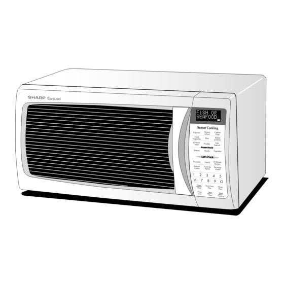
MICROWAVE OVEN
R-330EK
R-330EW
This document has been published to be used for after
sales service only.
The contents are subject to change without notice.
R - 33 0 EK
R-330EW
S3109R330EPW/
Page
Advertisement
Table of Contents

Related Manuals for Sharp R-330EK


Summary of Contents for Sharp R-330EK
-
Page 1: Table Of Contents
R - 33 0 EK R-330EW SERVICE MANUAL S3109R330EPW/ MICROWAVE OVEN R-330EK MODELS R-330EW Sensor Cooking Sensor Custom Popcorn reheat Help Fresh Rice Baked Vegetables potatoes Ground Fish Poultry meat Seafood Frozen Foods Frozen Foods Entrees Snacks Vegetables Let's Cook... -
Page 2: Precautions To Be Observed Before And During Servicing To Avoid Possible Exposure To Excessive Microwave Energy
Before servicing an operative unit, perform a microwave emission check as per the Microwave Measurement Procedure outlined in this service manual. If microwave emissions level is in excess of the specified limit, contact SHARP ELECTRONICS CORPORATION immediately @1-800-237-4277. If the unit operates with the door open, service person should 1) tell the user not to operate the oven and 2) contact SHARP ELECTRONICS CORPORATION and Food and Drug Administration's Center for Devices and Radiological Health immediately. -
Page 3: Warning To Service Personnel
R-330EK R-330EW WARNING TO SERVICE PERSONNEL Microwave ovens contain circuitry capable of pro- ducing very high voltage and current, contact with following parts may result in a severe, possibly fatal, electrical shock. (Example) High Voltage Capacitor, High Voltage Power Trans- former, Magnetron, High Voltage Rectifier Assem- bly, High Voltage Harness etc.. -
Page 4: Microwave Measurement Procedure
R- 330 EK R-330EW MICROWAVE MEASUREMENT PROCEDURE A. Requirements: 1) Microwave leakage limit (Power density limit): The power density of microwave radiation emitted by a microwave oven should not exceed 1mW/cm at any point 5cm or more from the external surface of the oven, measured prior to acquisition by a purchaser, and thereafter (through the useful life of the oven), 5 mW/cm at any point 5cm or more from the external surface of the oven. - Page 5 MICROWAVE OVEN R-330EK/ R-330EW GENERAL INFORMATION FOREWORD This Manual has been prepared to provide Sharp Electronics Corp. Service Personnel with Operation and Service Information for the SHARP MICROWAVE OVEN,R-330EK, R-330EW. OPERATION It is recommended that service personnel carefully study the entire text of this manual so that they will be qualified to render satisfactory customer service.
-
Page 6: General Information
R- 330 EK R-330EW SPECIFICATION ITEM DESCRIPTION Power Requirements 120 Volts / 14.2 Amperes 60 Hertz Single phase, 3 wire grounded Power Output 1200 watts (IEC TEST PROCEDURE) Operating frequency of 2450MHz Case Dimensions Width 20-1/2" Height 11-7/8" Depth 17-1/8" Cooking Cavity Dimensions Width 14-3/4"... - Page 7 R-330EK R-330EW contact a qualified electrician and have it replaced with a properly Grounded 3-Pronged Plug grounded three-pronged wall receptacle or have a grounding adapter Receptacle Box properly grounded and polarized. If the extension cord must be used, it should be a 3-wire, 15 amp. or higher rated cord. Do not drape over a countertop or table where it can be pulled on by children or tripped over accidentally.
-
Page 8: Operation
(Figure O-1). If the secondary interlock switch and primary interlock relay The display will show "SHARP SIMPLY THE BEST PRESS (RY2) fail with the contacts closed when the door is opened, CLEAR AND PRESS CLOCK".To set any program or set the closing of the monitor switch contacts will form a short the clock, you must first touch the STOP/CLEAR pad. - Page 9 R-330EK R-330EW An example of how sensor works: (POTATOES) The following is the sensor cooking menu. Popcorn, Sensor reheat, Fresh Vegetables, Rice, Baked potatoes, Ground meat, Poultry, Fresh Seafood, Frozen foods (Entrees, Snacks, Vegetables), From the Pantry (Beef Wraps, Mexican Chicken, Italian Salad, Tuna Maca-...
- Page 10 R- 330 EK R-330EW SCHEMATIC NOTE: CONDITION OF OVEN 1. DOOR CLOSED 2. CLOCK APPEARS ON DISPLAY THERMAL MONITOR THERMAL CUT-OUT (OVEN) FUSE 20A CUT-OUT (MG.) N.O. POWER N.O. TRANSFORMER (RY-2) (RY-1) PRIMARY INTERLOCK RELAY CONTROL UNIT COM. COM. SH-B SH-A 120V AC DOOR...
- Page 11 R-330EK R-330EW DESCRIPTION AND FUNCTION OF COMPONENTS DOOR OPEN MECHANISM CAUTION: BEFORE REPLACING A BLOWN MONITOR FUSE TEST THE DOOR SENSING SWITCH, The door is opened by pulling the door. Refer to the Figure PRIMARY INTERLOCK RELAY (RY2), RELAY D-1.
-
Page 12: Troubleshooting Guide
R- 330 EK R-330EW TROUBLESHOOTING GUIDE Never touch any part in the circuit with your hand or an uninsulated tool while the power supply is connected. When troubleshooting the microwave oven, it is helpful to follow the Sequence of Operation in performing the checks. Many of the possible causes of trouble will require that a specific test be performed. -
Page 13: Test Procedure
R-330EK R-330EW CK = Check / RE = Replace RE RE A B C D E F F G H RE RE CK I CK CK CK J K L M N TEST PROCEDURE PROBLEM CONDITION Home fuse or circuit breaker blows when power cord is plugged into wall receptacle. - Page 14 R- 330 EK R-330EW TEST PROCEDURES PROCEDURE COMPONENT TEST LETTER MAGNETRON ASSEMBLY TEST 1. Disconnect the power supply cord, and then remove outer case. 2. Open the door and block it open. 3. Discharge high voltage capacitor. 4. To test for an open filament, isolate the magnetron from the high voltage circuit. A continuity check across the magnetron filament leads should indicate less than 1 ohm.
- Page 15 R-330EK R-330EW TEST PROCEDURES PROCEDURE COMPONENT TEST LETTER (HIGH VOLTAGES ARE PRESENT AT THE HIGH VOLTAGE TERMINAL, SO DO NOT ATTEMPT TO MEASURE THE FILAMENT AND HIGH VOLTAGE.) HIGH VOLTAGE RECTIFIER TEST 1. Disconnect the power supply cord, and then remove outer case.
- Page 16 R- 330 EK R-330EW TEST PROCEDURES PROCEDURE COMPONENT TEST LETTER 5. Reconnect all leads removed from components during testing. 6. Reinstall the outer case (cabinet). 7. Reconnect the power supply cord after the outer case is installed. 8. Run the oven and check all functions. CAUTION: IF THE THERMAL CUT-OUT INDICATES AN OPEN CIRCUIT AT ROOM TEMPERATURE, REPLACE THERMAL CUT-OUT.
- Page 17 R-330EK R-330EW TEST PROCEDURES PROCEDURE COMPONENT TEST LETTER actuator is pushed by a screw driver through the lower latch hole on the front plate of the oven cavity with the door opened (in this condition the plunger of the monitor switch is pushed in), the meter should indicate an open circuit.
- Page 18 R- 330 EK R-330EW TEST PROCEDURES PROCEDURE COMPONENT TEST LETTER 3) Re-install the outer case (cabinet). 4) Reconnect the power supply cord after the outer case is installed. 5) Run the oven and check all functions. The following symptoms indicate a defective key unit. a) When touching the pads, a certain pad produces no signal at all.
- Page 19 R-330EK R-330EW TEST PROCEDURES PROCEDURE COMPONENT TEST LETTER If the control unit responds by clearing with a beep the key unit is faulty and must be replaced. If the control unit does not respond, it is faulty and must be replaced. If a specific pad does not respond, the above method may be used (after clearing the control unit) to determine if the control unit or key pad is at fault.
- Page 20 R- 330 EK R-330EW TEST PROCEDURES PROCEDURE COMPONENT TEST LETTER MENU 1ST STAGE 2ND STAGE Steaks, chops or fish LEVEL TIME LEVEL TIME 0.5lb 37sec. 30sec. (5) If improper operation is indicated, the control unit is probably defective and should be checked. FOIL PATTERN ON THE PRINTED WIRING BOARD TEST To protect the electronic circuits, this model is provided with a fine foil pattern added to the primary on the PWB, this foil pattern acts as a fuse.
- Page 21 R-330EK R-330EW TEST PROCEDURES PROCEDURE COMPONENT TEST LETTER 11) Reconnect all leads removed from components during testing. 12) Re-install the outer case (cabinet). 13) Reconnect the power supply cord after the outer case is installed. 14) Run the oven and check all functions.
- Page 22 R- 330 EK R-330EW TEST PROCEDURES PROCEDURE COMPONENT TEST LETTER 9-3. Close the door. 9-4. Touch the TIMER/CLOCK pad once, the POWER LEVEL pad twice, the START pad once and the number pads 1 once. 9-5. The control panel is in automatic Sensor operation. 9-6.
-
Page 23: Touch Control Panel
R-330EK R-330EW TOUCH CONTROL PANEL ASSEMBLY OUTLINE OF TOUCH CONTROL PANEL 3) Power Source Circuit The touch control section consists of the following units. This circuit generates voltages necessary in the control (1) Key Unit unit from the AC line voltage. - Page 24 R- 330 EK R-330EW LSI(IXA098DR) The I/O signal of the LSI(IXA098DR) is detailed in the following table. Pin No. Signal Description COM5 Common data signal : COM11. Connected to LCD signal COM11. COM4 Common data signal : COM12. Connected to LCD signal COM12. COM3 Common data signal : COM13.
- Page 25 R-330EK R-330EW Pin No. Signal Description INT0 Signal synchronized with commercial power source frequency. H : GND This is the basic timing for time processing of LSI. L : -5V 16.7 msec. Key strobe signal. Signal applied to touch-key section. A pulse signal is input to AIN7, P14, P15, P16, P17 and AIN6 terminal while one of G1 line keys on key matrix is touched.
- Page 26 R- 330 EK R-330EW Pin No. Signal Description XCOUT Terminal not used. XCIN Connected to VC. Terminal not used. Power source voltage: GND(0V). The power source voltage to drive LSI is input to VCC terminal. OSCSEL Connected to VC(-5V). XOUT Internal clock oscillation output.
- Page 27 R-330EK R-330EW ABSOLUTE HUMIDITY SENSOR CIRCUIT (1) Structure of Absolute Humidity Sensor resistance balance of the bridge circuit is deviated to The absolute humidity sensor includes two thermistors increase the voltage available at AIN5 terminal of the as shown in the illustration. One thermistor is housed in LSI.
- Page 28 R- 330 EK R-330EW TOUCH CONTROL PANEL SERVICING transformer. 1. Precautions for Handling Electronic Components 4) Re-install the outer case (cabinet). This unit uses CMOS LSI in the integral part of the 5) Re-connect the power supply cord after the outer circuits.
-
Page 29: Component Replacement And Adjustment Procedure
WARNING FOR WIRING To prevent an electric shock, take the following pre- and Oven cavity. cautions. 3) Sharp edge: 1. Before wiring, Bottom plate, Oven cavity, Waveguide flange, 1) Disconnect the power supply cord. Chassis support and other metallic plate. -
Page 30: Pictorial Diagram
R- 330 EK R-330EW CAUTION: 1. DISCONNECT OVEN FROM POWER SUP NOTE: When replacing the outer case, the 2 special PLY BEFORE REMOVING OUTER CASE. Torx screws must be reinstalled in the same 2. DISCHARGE THE HIGH VOLTAGE CA- locations. PACITOR BEFORE TOUCHING ANY OVEN COMPONENTS OR WIRING. -
Page 31: Cpu Unit Circuit
R-330EK R-330EW 9. Now, the magnetron is free. 4. Reconnect the wire leads to the magnetron and thermal Reinstallation cut-out (MG). Refer to "PICTORIAL DIAGRAM" on page 1. Re-install the magnetron to waveguide flange with the four (4) screws. 5. Re-install outer case and check that the oven is operating 2. - Page 32 4. Where the corners have been snipped off bend corner 7. Now the turntable motor is free. areas flat. No sharp edges must be evident after removal 8. After replacement use the one (1) screw to fit the of the turntable motor cover.
- Page 33 R-330EK R-330EW DOOR SENSING SWITCH/SECONDARY INTERLOCK SWITCH AND MONITOR SWITCH REMOVAL Reinstallation 1. Disconnect the power supply cord and remove outer case. 1. Re-install each switch in its place. The secondary 2. Open the door and block it open. interlock/monitor switches are in the lower position and 3.
- Page 34 R- 330 EK R-330EW 9. Remove the four (4) screws holding the door panel to the door frame. 10.Release door panel from eight (8) tabs of door frame. Upper Oven 11.Now, door panel with sealer film is free. Upper Hinge Oven Hinge 12.Tear sealer film from door panel.
- Page 35 R-330EK R-330EW...
- Page 36 R- 330 EK R-330EW CN-C 12PIN LEAD WIRE HARNESS Q2 2SB1238 R4 27 R5 4.7k D1-D4 11ES1 CN-A 1SS270A 1SS270A – – R3 510 1/2w Q1 2SB1238 R2 680 1/2w SP1 PKM22EPT OVEN LAMP TURNTABLE MOTOR FAN MOTOR Q3 KRC243M BUZZER R6 3.3k OVEN LAMP...
- Page 37 R-330EK R-330EW...
- Page 38 R- 330 EK R-330EW (RED) (GREEN) CN - C SH - B SH - A B R1 (CN - B) (J2) (R9) (D10) (CN - D) (J1) CN - A Figure S-4. Printed Wiring Board of Power Unit...
-
Page 39: Parts List
Varistor (10G471K) VHEHZ161///-1 Zener diode (HZ16-1) 3- 2 DPWBFC167WRKZ CPU unit 3- 3 FPNLCB562WRKZ Control panel frame with key unit [R-330EK] 3- 3 FPNLCB563WRKZ Control panel frame with key unit [R-330EW] 3- 3-1 FUNTKB053WREZ Key unit [R-330EK] 3- 3-1 FUNTKB054WREZ... - Page 40 DOOR PARTS ∆ 5- 1 FDORFA332WRT0 Door panel 5- 2 PSHEPA382WRE0 Sealer film ∆ 5- 3 FWAKPA322WRRZ Door frame assembly [R-330EK] ∆ 5- 3 FWAKPA323WRRZ Door frame assembly [R-330EW] 5- 3-1 GCOVPA011WRFZ Handle cover A 5- 4 HPNL-A756WRRZ Door screen [R-330EK] ∆...
-
Page 41: Packing And Accessories
1. MODEL NUMBER 2. REF. NO. 3. PART NO. 4. DESCRIPTION Order Parts from the authorized SHARP parts Distributor for your area. Defective parts requiring return should be returned as indicated in the Service Policy. PACKING AND ACCESSORIES TOP PAD ASSEMBLY... - Page 42 R - 330 EK R-330EW OVEN AND CABINET PARTS 4-23 4-25 4-22 1-15 7-10 1-11 1-10 4-17 4-20 4-13 4-24 4-23 4-11 4-10 4-21 4-19 4-22 4-12 4-21 4-15 1-13 4-14 4-26 1-12 4-18 1-14 4-16 4-15...
- Page 43 R - 33 0 EK R-330EW CONTROL PANEL PARTS DOOR PARTS 5-11 3-3-1 5-10 5-10 5-3-1 MISCELLANEOUS (CAPACITOR) Actual wire harness may be different from illustration.
- Page 44 No part of this publication may be reproduced, stored in retrieval systems, or transmitted in any form or by any means, electronic, mechanical, photocopying, recording, or otherwise, without prior written permission of the publisher. 2001 SHARP CORP. (3S2.530E) Printed in U.S.A...
Need help?
Do you have a question about the R-330EK and is the answer not in the manual?
Questions and answers