Table of Contents
Advertisement
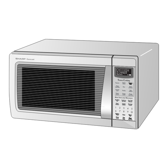
R-330DW
BEFORE SERVICING ...................................................................................................... INSIDE FRONT COVER
WARNING TO SERVICE PERSONNEL ................................................................................................................ 1
MICROWAVE MEASUREMENT PROCEDURE ................................................................................................... 2
FOREWORD AND WARNING ............................................................................................................................... 3
PRODUCT SPECIFICATIONS .............................................................................................................................. 4
GENERAL INFORMATION ................................................................................................................................... 4
OPERATION .......................................................................................................................................................... 6
TROUBLESHOOTING GUIDE ............................................................................................................................ 10
TEST PROCEDURE ............................................................................................................................................ 12
TOUCH CONTROL PANEL ................................................................................................................................. 21
COMPONENT REPLACEMENT AND ADJUSTMENT PROCEDURE ................................................................ 26
PICTORIAL DIAGRAM ........................................................................................................................................ 32
POWER UNIT CIRCUIT ...................................................................................................................................... 33
CPU UNIT CIRCUIT ............................................................................................................................................ 34
INDICATOR CIRCUIT .......................................................................................................................................... 35
PRINTED WIRING BOARD ................................................................................................................................. 36
PARTS LIST ........................................................................................................................................................ 37
PACKING AND ACCESSORIES ......................................................................................................................... 41
SHARP CORPORATION
SERVICE MANUAL
MODELS
In the interest of user-safety the oven should be restored to its original
condition and only parts identical to those specified should be used.
WARNING TO SERVICE PERSONNEL: Microwave ovens con-
tain circuitry capable of producing very high voltage and
current, contact with following parts may result in a severe,
possibly fatal, electrical shock. (High Voltage Capacitor, High
Voltage Power Transformer, Magnetron, High Voltage Recti-
fier Assembly, High Voltage Harness etc..)
TABLE OF CONTENTS
This document has been published to be used for after
sales service only.
The contents are subject to change without notice.
MICROWAVE OVEN
R-330DK
R-330DW
R - 330DK
R -330DW
S3005R330DPW/
Page
Advertisement
Table of Contents

Related Manuals for Sharp R-330DK


Summary of Contents for Sharp R-330DK
-
Page 1: Table Of Contents
R - 330DK R -330DW SERVICE MANUAL S3005R330DPW/ MICROWAVE OVEN R-330DK MODELS R-330DW In the interest of user-safety the oven should be restored to its original condition and only parts identical to those specified should be used. R-330DW WARNING TO SERVICE PERSONNEL: Microwave ovens con-... -
Page 2: Precautions To Be Observed Before And During Servicing To Avoid Possible Exposure To Excessive Microwave Energy
Before servicing an operative unit, perform a microwave emission check as per the Microwave Measurement Procedure outlined in this service manual. If microwave emissions level is in excess of the specified limit, contact SHARP ELECTRONICS CORPORATION immediately @1-800-237-4277. If the unit operates with the door open, service person should 1) tell the user not to operate the oven and 2) contact SHARP ELECTRONICS CORPORATION and Food and Drug Administration's Center for Devices and Radiological Health immediately. -
Page 3: Warning To Service Personnel
R -330DK R-330DW WARNING TO SERVICE PERSONNEL Microwave ovens contain circuitry capable of pro- ducing very high voltage and current, contact with following parts may result in a severe, possibly fatal, electrical shock. (Example) High Voltage Capacitor, High Voltage Power Trans- former, Magnetron, High Voltage Rectifier Assem- bly, High Voltage Harness etc.. -
Page 4: Microwave Measurement Procedure
R- 330DK R-330DW MICROWAVE MEASUREMENT PROCEDURE A. Requirements: 1) Microwave leakage limit (Power density limit): The power density of microwave radiation emitted by a microwave oven should not exceed 1mW/cm at any point 5cm or more from the external surface of the oven, measured prior to acquisition by a purchaser, and thereafter (through the useful life of the oven), 5 mW/cm at any point 5cm or more from the external surface of the oven. - Page 5 MICROWAVE OVEN R-330DK/ R-330DW GENERAL INFORMATION FOREWORD This Manual has been prepared to provide Sharp Electronics Corp. Service Personnel with Operation and Service Information for the SHARP MICROWAVE OVEN, R-330DK, R-330DW. OPERATION It is recommended that service personnel carefully study the entire text of this manual so that they will be qualified to render satisfactory customer service.
-
Page 6: General Information
R- 330DK R-330DW SPECIFICATION ITEM DESCRIPTION Power Requirements 120 Volts / 14 Amperes 60 Hertz Single phase, 3 wire grounded Power Output 1150 watts (IEC TEST PROCEDURE) Operating frequency of 2450MHz Case Dimensions Width 20-1/2" Height 11-7/8" Depth 17-1/8" Cooking Cavity Dimensions Width 14-3/4"... -
Page 7: Oven Diagram
R -330DK R-330DW contact a qualified electrician and have it replaced with a properly grounded three-pronged wall receptacle or have a grounding adapter Grounded 3-Pronged Plug Receptacle Box properly grounded and polarized. If the extension cord must be used, it should be a 3-wire, 15 amp. -
Page 8: Operation
(Figure O-1). If the secondary interlock switch and primary interlock relay 1. The display will show "SHARP SIMPLY THE BEST (RY2) fail with the contacts closed when the door is opened, PRESS CLEAR AND PRESS CLOCK".To set any... - Page 9 R -330DK R-330DW An example of how sensor works: (POTATOES) 1. Potates at room temperature. Vapor is emitted very slowly. 2. Heat Potates. Moisture and humidity is emitted rapidly. You can smell the aroma as it cooks. AH SENSOR 3. Sensor detects moisture and humidity and calculates cooking time and variable power.
- Page 10 R- 330DK R-330DW SCHEMATIC NOTE: CONDITION OF OVEN 1. DOOR CLOSED 2. CLOCK APPEARS ON DISPLAY THERMAL MONITOR THERMAL CUT-OUT (OVEN) FUSE 20A CUT-OUT (MG.) N.O. POWER N.O. TRANSFORMER (RY-1) (RY-2) PRIMARY INTERLOCK RELAY CONTROL UNIT COM. COM. SH-B SH-A 120V AC 60 Hz DOOR...
- Page 11 R -330DK R-330DW DESCRIPTION AND FUNCTION OF COMPONENTS DOOR OPEN MECHANISM CAUTION: BEFORE REPLACING A BLOWN MONITOR FUSE TEST THE DOOR SENSING SWITCH, The door is opened by pulling the door. Refer to the Figure PRIMARY INTERLOCK RELAY (RY2), RELAY D-1.
-
Page 12: Troubleshooting Guide
R- 330DK R-330DW TROUBLESHOOTING GUIDE Never touch any part in the circuit with your hand or an uninsulated tool while the power supply is connected. When troubleshooting the microwave oven, it is helpful to follow the Sequence of Operation in performing the checks. Many of the possible causes of trouble will require that a specific test be performed. -
Page 13: Test Procedure
R -330DK R-330DW CK = Check / RE = Replace RE RE A B C D E F F G H RE RE CK I CK CK CK J K L M N TEST PROCEDURE PROBLEM CONDITION Home fuse or circuit breaker blows when power cord is plugged into wall receptacle Monitor fuse blows when power cord... - Page 14 R- 330DK R-330DW TEST PROCEDURES PROCEDURE COMPONENT TEST LETTER MAGNETRON ASSEMBLY TEST 1. Disconnect the power supply cord, and then remove outer case. 2. Open the door and block it open. 3. Discharge high voltage capacitor. 4. To test for an open filament, isolate the magnetron from the high voltage circuit. A continuity check across the magnetron filament leads should indicate less than 1 ohm.
- Page 15 R -330DK R-330DW TEST PROCEDURES PROCEDURE COMPONENT TEST LETTER (HIGH VOLTAGES ARE PRESENT AT THE HIGH VOLTAGE TERMINAL, SO DO NOT ATTEMPT TO MEASURE THE FILAMENT AND HIGH VOLTAGE.) HIGH VOLTAGE RECTIFIER TEST 1. Disconnect the power supply cord, and then remove outer case. 2.
- Page 16 R- 330DK R-330DW TEST PROCEDURES PROCEDURE COMPONENT TEST LETTER 6. Reinstall the outer case (cabinet). 7. Reconnect the power supply cord after the outer case is installed. 8. Run the oven and check all functions. CAUTION: IF THE THERMAL CUT-OUT INDICATES AN OPEN CIRCUIT AT ROOM TEMPERATURE, REPLACE THERMAL CUT-OUT.
- Page 17 R -330DK R-330DW TEST PROCEDURES PROCEDURE COMPONENT TEST LETTER indicate an open circuit. If improper operation is indicated, the switch may be defective. After testing the monitor switch, reconnect the wire lead to the monitor switch (COM) terminal and check the continuity of the monitor circuit.
- Page 18 R- 330DK R-330DW TEST PROCEDURES PROCEDURE COMPONENT TEST LETTER 5) Run the oven and check all functions. The following symptoms indicate a defective key unit. a) When touching the pads, a certain pad produces no signal at all. b) When touching a number pad, two figures or more are displayed. c) When touching the pads, sometimes a pad produces no signal.
- Page 19 R -330DK R-330DW TEST PROCEDURES PROCEDURE COMPONENT TEST LETTER 5. Reconnect all leads removed from components during testing. 6. Re-install the outer case (cabinet). 7. Reconnect the power supply cord after the outer case is installed. 8. Run the oven and check all functions. Beverage center Compu...
- Page 20 R- 330DK R-330DW TEST PROCEDURES PROCEDURE COMPONENT TEST LETTER 1ST STAGE 2ND STAGE WEIGHT LEVEL TIME LEVEL TIME 0.5lb 40sec. 30sec. (5) If improper operation is indicated, the control unit is probably defective and should be checked. FOIL PATTERN ON THE PRINTED WIRING BOARD TEST To protect the electronic circuits, this model is provided with a fine foil pattern added to the primary on the PWB, this foil pattern acts as a fuse.
- Page 21 R -330DK R-330DW TEST PROCEDURES PROCEDURE COMPONENT TEST LETTER 12) Re-install the outer case (cabinet). 13) Reconnect the power supply cord after the outer case is installed. 14) Run the oven and check all functions. AH SENSOR TEST Checking the initial sensor cooking condition WARNING : The oven should be fully assembled before following procedure.
- Page 22 R- 330DK R-330DW TEST PROCEDURES PROCEDURE COMPONENT TEST LETTER 9-5. The control panel is in automatic Sensor operation. 9-6. The display will start to count down the remaining cooking time, and the oven will turn off automatically after the water is boiling (bubbling). If new sensor dose not operate properly, the problem is with the control unit, and refer to explanation below.
-
Page 23: Touch Control Panel
R -330DK R-330DW TOUCH CONTROL PANEL ASSEMBLY OUTLINE OF TOUCH CONTROL PANEL 3) Power Source Circuit The touch control section consists of the following units. This circuit generates voltages necessary in the control (1) Key Unit unit from the AC line voltage. (2) Control Unit (The Control Unit consists of Power Unit In addition, the synchronizing signal is available in order and LSI Unit). - Page 24 R- 330DK R-330DW Pin No. Signal Description RESET Auto clear terminal. Signal is input to reset the LSI to the initial state when power is applied. Temporarily set "L" level the moment power is applied, at this time the LSI is reset. Thereafter set at "H" level.
- Page 25 R -330DK R-330DW Pin No. Signal Description 28-31 ANI0-ANI3 Terminal to change cooking input according to the Model. By using the A/D converter contained in the LSI, DC voltage in accordance with the Model in operation is applied to set up its cooking constant. ANI4 Used for initial balancing of the bridge circuit (absolute humidity sensor).
- Page 26 R- 330DK R-330DW ABSOLUTE HUMIDITY SENSOR CIRCUIT (1) Structure of Absolute Humidity Sensor increase the voltage available at ANI5 terminal of the The absolute humidity sensor includes two thermistors LSI. as shown in the illustration. One thermistor is housed in Then the LSI observes that voltage at ANI5 terminal and the closed vessel filled with dry air while another in the compares it with its initial value, and when the comparison...
- Page 27 R -330DK R-330DW TOUCH CONTROL PANEL SERVICING 3) Re-connect the leads to the primary of the power 1. Precautions for Handling Electronic Components transformer. This unit uses CMOS LSI in the integral part of the 4) Re-install the outer case (cabinet). circuits.
-
Page 28: Component Replacement And Adjustment Procedure
WARNING FOR WIRING To prevent an electric shock, take the following pre- and Oven cavity. cautions. 3) Sharp edge: 1. Before wiring, Bottom plate, Oven cavity, Waveguide flange, 1) Disconnect the power supply cord. Chassis support and other metallic plate. -
Page 29: Pictorial Diagram
R -330DK R-330DW 2. DISCHARGE THE HIGH VOLTAGE CA- NOTE: When replacing the outer case, the 2 special PACITOR BEFORE TOUCHING ANY OVEN Torx screws must be reinstalled in the same COMPONENTS OR WIRING. locations. POWER TRANSFORMER REMOVAL 1. Disconnect the power supply cord and then remove Re-instal outer case. -
Page 30: Cpu Unit Circuit
R- 330DK R-330DW Reinstallation the four (4) screws. 1. Re-install the magnetron duct with thermal cut-out (MG) 5. Reconnect the wire leads to the magnetron and thermal to magnetron with the two (2) screws. cut-out (MG). Refer to "PICTORIAL DIAGRAM" on page 2. - Page 31 4. Where the corners have been snipped off bend corner 7. Now the turntable motor is free. areas flat. No sharp edges must be evident after removal 8. After replacement use the one (1) screw to fit the of the turntable motor cover.
- Page 32 R- 330DK R-330DW DOOR SENSING SWITCH/SECONDARY INTERLOCK SWITCH AND MONITOR SWITCH REMOVAL Reinstallation 1. Disconnect the power supply cord and remove outer case. 1. Re-install each switch in its place. The secondary 2. Open the door and block it open. interlock/monitor switches are in the lower position and 3.
- Page 33 R -330DK R-330DW 11.Now, door panel with sealer film is free. 12.Tear sealer film from door panel. 13.Now, door panel is free. 14.Slide latch head upward and remove it from door frame Upper Oven Upper Hinge with releasing latch spring from door frame and latch Oven Hinge head.
- Page 34 R- 330DK R-330DW RECTIFIER H.V.
- Page 35 R -330DK R-330DW CN-C 12PIN LEAD WIRE HARNESS Q2 2SB1238 R4 27 R5 4.7k D1-D4 11ES1 CN-A 1SS270A 1SS270A – – R3 510 1/2w Q1 2SB1238 R2 680 1/2w SP1 PKM22EPT OVEN LAMP TURNTABLE MOTOR FAN MOTOR Q3 KRC243M BUZZER R6 3.3k OVEN LAMP TURNTABLE...
- Page 36 R- 330DK R-330DW COM0 ANI2 COM1 ANI1 COM2 ANI0 COM3 AVSS BIAS P117 VLC0 P116 VLC1 P115 VLC2 P114 VSS0 P113 P112 P111 P110 INTP1 INTP0 RESET VDD1 G10 G11 G12 G13 G14 4.7K 330p/50v (J16) (J17) 330p/50v 4.7K 330p/50v 330p/50v (J14) (J15)
- Page 37 R -330DK R-330DW SENSOR DEFROST COOK HELP SEG9 SEG35 SEG8 SEG36 SEG7 SEG37 SEG6 SEG38 SEG5 SEG39 SEG4 COM16 SEG3 COM15 /50v SEG2 COM14 SEG1 COM13 C129 SEG0 COM12 COM7 COM11 COM6 COM10 COM5 COM9 COM4 COM8 COM3 COM2 COM1 COM0 OSC1 OSC2...
-
Page 38: Printed Wiring Board
R- 330DK R-330DW (RED) (GREEN) CN - C SH - B SH - A B R1 (CN - B) (J2) (D10) (J1) CN - A Figure S-5. Printed Wiring Board of Power Unit... -
Page 39: Parts List
Varistor (10G471K) VHEHZ161///-1 Zener diode (HZ16-1) 3- 2 DPWBFC025WRKZ CPU unit 3- 3 FPNLCB488WRKZ Control panel frame with key unit [R-330DK] 3- 3 FPNLCB489WRKZ Control panel frame with key unit [R-330DW] 3- 3-1 FUNTKA983WREZ Key unit [R-330DK] 3- 3-1 FUNTKA984WREZ... - Page 40 To have your order filled promptly and correctly, please furnish the following information. 1. MODEL NUMBER 2. REF. NO. 3. PART NO. 4. DESCRIPTION Order Parts from the authorized SHARP parts Distributor for your area. Defective parts requiring return should be returned as indicated in the Service Policy.
- Page 41 R - 330DK R -330DW OVEN AND CABINET PARTS 4-23 4-25 4-22 1-15 1-10 4-17 1-11 1-13 4-20 4-13 4-24 4-23 4-11 4-19 4-10 4-20 4-22 4-12 4-21 4-15 4-14 4-18 1-12 1-14 4-16 4-15...
- Page 42 R -3 30DK R-330DW CONTROL PANEL PARTS 3-3-1 DOOR PARTS MISCELLANEOUS (CAPACITOR) Actual wire harness may be different from illustration.
-
Page 43: Packing And Accessories
PLASTIC BAG SSAKHA034WRE0 6- 8 INSTRUCTION BOOK & PRINTING MATTER 6-10 RECIPE SHEET 6- 2 TURNTABLE TRAY BOTTOM PAD ASSEMBLY FPADBA417WRKZ 6- 1 TURNTABLE SUPPORT TRAY PACK INTO THE SPADFA451WRE0 OVEN CAVITY Not replaceable items. PACKING CASE SPAKCD361WREZ [R-330DK] SPAKCD362WREZ [R-330DW]... - Page 44 No part of this publication may be repro- duced, stored in retrieval systems, or trans- mitted in any form or by any means, elec- tronic, mechanical, photocopying, record- ing, or otherwise, without prior written per- mission of the publisher. 2000 SHARP CORP. (3S2.530E) Printed in U.S.A...
Need help?
Do you have a question about the R-330DK and is the answer not in the manual?
Questions and answers