Table of Contents
Advertisement
Quick Links
MITSUBISHI HEAVY INDUSTRIES THERMAL SYSTEMS, LTD.
16-5 Konan 2-chome, Minato-ku, Tokyo, 108-8215, Japan
http://www.mhi-mth.co.jp/en/
MITSUBISHI HEAVY INDUSTRIES - MAHAJAK AIR CONDITIONERS CO., LTD.
220 Lad Krabang Industrial Estate Free Zone 3, Soi Chalongkrung 31, Kwang Lamplatiew,
Khet Lad Krabang, Bangkok 10520, Thailand
Tel : +66-2-326-0401
Fax : +66-2-326-0419
http://www.maco.co.th/
RMA012A088A_B_Cover.indd 1
RMA012A088A_B_Cover.indd 1
USER'S MANUAL
&
INSTALLATION MANUAL
AIR-CONDITIONER
SRK10CRS-S3
SRK13CRS-S3
Terima kasih Anda telah membeli MITSUBISHI HEAVY INDUSTRIES THERMAL SYSTEMS, LTD.
Air Conditioner.
Untuk mendapatkan kinerja unit yang terbaik dan tahan lama, silakan Anda membaca dan mengikuti Buku
Pedoman Pengguna ini secara seksama sebelum menggunakan air-conditioner ini.
Selesai membaca, simpan kembali Buku Pedoman ini di tempat yang aman dan jadikan buku ini sebagai
bahan acuan jika ada yang belum jelas mengenai pengoperasian unit atau jika ada kelainan pada unit.
Air-conditioner ini hanya diperuntukkan di dalam ruangan.
Penyaman udara ini menggunakan R410A sahaja
Thank you for purchasing a MITSUBISHI HEAVY INDUSTRIES THERMAL SYSTEMS, LTD. Air Conditioner.
To get the best long-lasting performance, read and follow this User's Manual carefully before using your air-conditioner.
After reading, please store the Manual in a safe place and refer to it for operational questions or in the event
of any irregularities.
This air-conditioner is intended for domestic use.
This Air conditioner for use R410A only
I.15.GBT2.03502.0815
I.15.GBT2.05305.1115
ORIGINAL INSTRUCTIONS
ORIGINAL INSTRUCTIONS
BUKU PEDOMAN
PANDUAN PEMASANGAN
USER'S MANUAL
INSTALLATION MANUAL
RMA012A088A
B
12/7/2018 1:59:04 PM
12/7/2018 1:59:04 PM
Advertisement
Chapters
Table of Contents

Related Manuals for Mitsubishi Heavy Industries SRK10CRS-S3


Summary of Contents for Mitsubishi Heavy Industries SRK10CRS-S3
- Page 1 MITSUBISHI HEAVY INDUSTRIES - MAHAJAK AIR CONDITIONERS CO., LTD. Penyaman udara ini menggunakan R410A sahaja Thank you for purchasing a MITSUBISHI HEAVY INDUSTRIES THERMAL SYSTEMS, LTD. Air Conditioner. 220 Lad Krabang Industrial Estate Free Zone 3, Soi Chalongkrung 31, Kwang Lamplatiew, To get the best long-lasting performance, read and follow this User’s Manual carefully before using your air-conditioner.
-
Page 2: Table Of Contents
USER’S MANUAL contents Safety precautions .........................2 Choice of operations and features ....................6 Name of each part and its function ....................7 Operation and indication section for remote control ..............9 AUTO mode operation procedure ....................10 Temperature adjustment during AUTO ..................10 About FAN SPEED ........................10 COOL/DRY/FAN mode operation procedure ................11 Air-conditioner operating conditions ..................11 Air fl... -
Page 3: Safety Precautions
Safety precautions • Before starting to use the system, please read these “Safety precautions” carefully to ensure proper operation of the system. • When you have read this instruction manual, please keep it without missing. If someone else takes over as operator, make sure that the manual is also passed on to the new operator. Improper handling could lead to drastic result like death, serious WARNING injury, etc. - Page 4 ❚ Safety precautions ❚ Safety precautions ❚ OPERATION PRECAUTIONS WARNING • • Children shall not play with the Cleaning and user maintenance shall appliance. not be made by children without • supervision. Do not expose yourself to the cooling • air for a long period.
- Page 5 ❚ Safety precautions CAUTION • • Do not touch the aluminum fi ns on the Do not shut off the power supply air heat exchanger. immediately after stopping the operation. It may result in injury. • Do not place household electrical Wait at least 5 minutes, otherwise there is appliances or household items a risk of water leakage or breakdown.
- Page 6 ❚ Safety precautions ❚ PRECAUTIONS FOR RELOCATION OR REPAIRS WARNING • Do not perform any repairs or modifi cations by yourself. Consult the dealer if the unit requires repair. If you repair or modify the unit, it can cause water leaks, electric shocks or fi re. •...
-
Page 7: Choice Of Operations And Features
Choice of operations and features Choice of operations Page 11 Page 11 COOL Cooling by extracting heat from the room. Drying by extracting damp from the room. Functioning of microcomputer depends on setting and room tem- peratures. It dehumidifi es while keeping room temperature almost constant. -
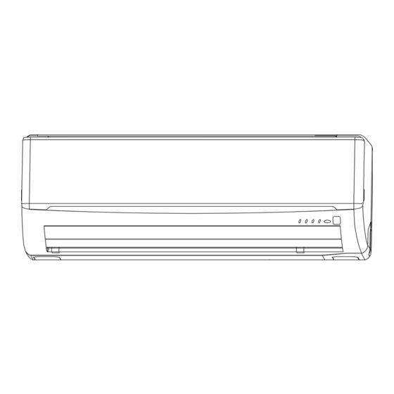
Page 8: Name Of Each Part And Its Function
Name of each part and its function INDOOR UNIT Air inlet panel Unit indication section and remote control signal receiver Wireless remote control Air fi lter Removes dust or dirt from the inlet air. Page 20 Air-cleaning fi lter Room temperature detector Unit operation switch Air outlet Air blows out of here. - Page 9 RUN light (green) Illuminates during operation and CLEAN operation. TIMER light (yellow) Illuminates during TIMER operation. HI POWER light (green) Illuminates during HIGH POWER operation. 3D AUTO light (green) Illuminates during 3D AUTO operation. Page 17 – 8 – RMA012A088A_089A_RevB_EN.indb 8 RMA012A088A_089A_RevB_EN.indb 8 11/19/2018 4:05:02 PM 11/19/2018 4:05:02 PM...
-
Page 10: Operation And Indication Section For Remote Control
Operation and indication section for remote control Operation section FAN SPEED button OPERATION MODE select button Each time the button is pushed, the Each time the button is pressed, the indicator is switched over in turn. indicator is switched over in turn. ON/OFF (luminous) button HI POWER/ECONO button Press for starting operation, press again... -
Page 11: Auto Mode Operation Procedure
AUTO mode operation procedure ■ Automatically selects the operation mode (COOL, DRY) depending on the room temperature when switched on. When the unit is not in AUTO mode: Press MODE button. Move the [ mark] to the (Auto) position. Aim the remote control at the air-conditioner. Press the ON/OFF button. -
Page 12: Cool/Dry/Fan Mode Operation Procedure
COOL/DRY/FAN mode operation procedure Aim the remote control at the air-conditioner. Press the MODE select button. Move the [ mark] to the desirable operation position. (Cool), (Fan), (Dry) Press the ON/OFF button. Press the TEMP button. Press button for the desired temperature. Recommendation 26°C~28°C 21°C~24°C... -
Page 13: Air Fl Ow Direction Adjustment Procedure
Air fl ow direction adjustment procedure Adjusting air fl ow direction ■ Up/down direction can be adjusted with the AIRFLOW (UP/DOWN) button on the remote control. Each time when you press this button the mode changes as follows: Change to AIRFLOW (UP/DOWN) mode. (Flap stopped) (Swing) ■... -
Page 14: Sleep Operation Procedure
SLEEP operation procedure ■ The unit stops automatically at the end of the set period of time. The room temperature is automatically controlled when the set time lapses, so that the room does not become too cold during cooling. Page 15 Press the SLEEP button. -
Page 15: On-Timer Operation Procedure
ON-TIMER operation procedure ■ Operation starts 5 to 60 minutes before the time that is set so that the room temperature reaches the optimum temperature at that time. Page 15 ON-TIMER operation can be set regardless of whether the air-conditioner is running or not. Example: In the case you wish to bring the temperature to nearly set temperature in at 8:00. -
Page 16: Program Timer Operation Procedure
PROGRAM TIMER operation procedure ■ The timer operations that consist of the combination of the timer being set at both on and off. Once this has been set and operations started, operations will commence and end at the same time every day as long as the ON/OFF button is not pressed. Example: When it is desired to stop at 22:30, and then start operation at 8:00, near the set temperature. -
Page 17: High Power/Economy Operation Procedure
HIGH POWER/ECONOMY operation procedure If the air-conditioner is not operating, aim the remote control at the air-conditioner. Press the ON/OFF button. Press the HI POWER/ECONO button. • When the operating mode is AUTO or COOL Each time the HI POWER/ECONO button is pressed, the indicator is switched in the order of: (HIGH POWER) (ECONOMY) -
Page 18: Concerning Clean Operation
Concerning CLEAN operation ■ CLEAN operation should be run after AUTO, COOL and DRY operation to remove the moisture from inside the indoor unit and control the growth of mold and bacteria. Press the CLEAN switch with the tip of a ballpoint pen. Each time the CLEAN switch is pressed, the indicator is switched in the order of: No indication... -
Page 19: Installation Location Setting
Installation location setting Take the air conditioning unit’s location into account and adjust the left/right airflow range to maximize air-conditioning. If the air conditioning unit is running, press the ON/OFF button to stop. The installation location setting cannot be made while the unit is running. Press the AIR FLOW (UP/DOWN) button and the AIRFLOW... -
Page 20: Remote Control Handling Procedure
Remote control handling procedure Using the remote control holder Replacing the batteries The following cases signify exhausted batteries. Replace old batteries with new ones. • Receiving beep is not emitted when a signal is transmitted. The remote control can be attached to a •... -
Page 21: Operating Hints
Operating hints ■ Please observe the following for the most economic and comfortable use of your unit. Set a suitable room temperature. Clean the fi lters frequently. Avoid direct sunlight and draught. suitable temperature Excessively low temperatures are not good Clogged fi... - Page 22 Cooling is affected by an air fi lter clogged up with dust etc., and the operation noise becomes louder. It may also use NOTE extra electricity. Please clean the air fi lter at appropriate intervals. At the end of the season At the beginning of the season Perform the fan operation for a half day.
-
Page 23: Has The Unit Been Installed Correctly
Has the unit been installed correctly? Suitable installation position • Is there any obstruction in front of the indoor unit, preventing proper ventilation and functioning? • Don’t install the unit in any of the following places: • Where there is a danger of leaking infl ammable gases. •... -
Page 24: Please Remember
Please remember! You cannot restart the unit immediately after you have Restarting has been blocked for 3 minutes after you have stopped or stopped it. after switching off the power during operation, to protect the unit. (RUN light is on) Please wait for three minutes. -
Page 25: When To Contact Your Distributor Without Delay
When to contact your distributor without delay ■ Turn off the power switch immediately and inform your dealer in any of the following situations: The fuse or switch blows continu- The cable becomes extremely hot. ously. The covering of the cable is cracked. CAUTION Fuse often blows. - Page 26 INSTALLATION MANUAL Contents Safety precautions ........................26 Selection of installation location ....................28 Installation of indoor unit ......................29 Installation of outdoor unit ......................32 Connection of refrigerant pipings ....................32 How to relocate or dispose of the unit ..................33 Installation of remote control switch ..................34 Earthing work ..........................34 Trial run and operation ........................34 Installations test check points .....................34...
-
Page 27: Safety Precautions
While install the unit, be sure to check the selection of installation place, power supply speci- WALL TYPE AIR CONDITIONER fi cations, usage limitation (piping length, height differences between indoor and outdoor units, R410A REFRIGERANT USED power supply voltage and etc.) and installation spaces. Safety precautions •... - Page 28 ❚ Safety precautions CAUTION • Carry out the electrical work for ground lead with care. Do not connect the ground lead to the gas line, water line, lightning conductor or telephone line’s ground lead. Incorrect grounding can cause unit faults such as electric shocks due to short-circuiting. •...
-
Page 29: Selection Of Installation Location
Standard accessories Necessary tools for the installation work (Installation kit) Q'ty Accessories for indoor unit Plus headed driver (Phillips screwdriver) Installation board Knife (Attached to the rear of the indoor unit) Wireless remote control Tape measure Remote contorol holder Hammer Tapping screws Spanner wrench (for installation board 4dia. -
Page 30: Installation Of Indoor Unit
Limitations for one way piping length and vertical height difference One way piping length ( ) 15 m Outdoor unit is 10 m lower Vertical height difference (h) Outdoor unit is 10 m higher Installation of indoor unit Installation of installation board Look for the inside wall structures (Intermediate support or INSTALLATION SPACE (INDOOR UNIT) (FRONT VIEW) - Page 31 Preparation of indoor unit 1 Mounting of connecting wires a Remove the lid. b Remove the wiring clamp. c Connect the connecting wire securely to the terminal block. Use cable for interconnection wiring to avoid loosening of the wires. CENELEC code for cables Required field cables. Harmonized cable type 05 300/500 volts Natural-and/or synth.
- Page 32 Open/close and detachment/attachment of air inlet panel 1 To open, pull the panel at both ends of lower part and release latches, then pull up the panel until you feel resistance. (The air inlet panel stops at approx. 60˚ open position.) 2 To close, hold the panel at both ends of lower part to lower downward and push it slightly until the latch works, then push the center portion slightly.
-
Page 33: Installation Of Outdoor Unit
Installation of outdoor unit 1 Make sure that the unit is stable in installation. Fix the unit to stable base. 2 Perform wiring, making wire terminal numbers conform to terminal numbers of indoor unit Terminal block terminal block. ! Brown For power supply, indoor outdoor ±... -
Page 34: How To Relocate Or Dispose Of The Unit
Air purge 1 Tighten all fl are nuts in the pipings both indoor and outside wall so as not to cause leak. Compound pressure gauge Pressure gauge 2 Connect operation valve, charge hose, manifold Operation valve cap Gauge manifold Operation valve valve and vacuum pump as is illustrated right. -
Page 35: Installation Of Remote Control Switch
Installation of remote control switch Mounting method of battery Fixing to pillar or wall • • Uncover the remote control switch, and mount the batter- Conventionally, operate the wireless remote control by ies [R03(AAA, Micro)×2 pieces] in the body regularly. holding in your hand.
Need help?
Do you have a question about the SRK10CRS-S3 and is the answer not in the manual?
Questions and answers