
Related Manuals for GEA EL66


Summary of Contents for GEA EL66
- Page 1 Liquid manure spreader EL66 Operation Manual (Original instructions) 2018-9015-005 09-2016 gea.com...
-
Page 2: Table Of Contents
..............GEA Farm Technologies Canada Inc. / Division GEA Houle - General Equipment Warranty . - Page 3 Operating ............. . . Special personnel qualification required for operation .
-
Page 4: Preface
Preface About the Instructions Preface This is a GEA product. GEA is the manufacturer of the Houle product line. This product was formerly known under HOULE trademark. About the Instructions The manufacturer reserves the right to make changes due to technical developments in the data and images given in this manual. -
Page 5: Manufacturer's Address
Preface Customer service Manufacturer's address GEA Farm Technologies GmbH Siemensstraße 25-27 D-59199 Bönen +49 (0) 2383 / 93-70 +49 (0) 2383 / 93-80 contact@gea.com www.gea.com Customer service Authorized Technical Dealer If necessary, please contact your nearest dealer. There is a comprehensive dealer Internet search function on our website at the following address: www.gea.com... -
Page 6: Declaration Of Conformity
The undersigned is acting by virtue of power of attorney from the management of: GEA Farm Technologies GmbH, Siemensstraße 25-27, D-59199 Bönen This declaration certifies compliance with the guidelines indicated, but does not establish any guarantee in the sense of paragraphs 443, 444 BGB. -
Page 7: Gea Farm Technologies Canada Inc. / Division Gea Houle - General Equipment Warranty
Preface GEA Farm Technologies Canada Inc. / Division GEA Houle - General Equipment Warranty GEA Farm Technologies Canada Inc. / Division GEA Houle - General Equipment Warranty Important notice! THIS GENERAL WARRANTY APPLIES TO ALL EQUIPMENT SOLD UNDER THE GEA HOULE TRADEMARK. - Page 8 Preface GEA Farm Technologies Canada Inc. / Division GEA Houle - General Equipment Warranty 1.5.3 Extent of Limited Warranty This limited warranty DOES NOT cover: ● Defects caused by negligence of the Purchaser in the maintenance of the equipment, improper use resulting from failure to adhere strictly to the...
- Page 9 Preface GEA Farm Technologies Canada Inc. / Division GEA Houle - General Equipment Warranty 1.5.4 Warranty Limitations and Exclusion NO WARRANTY, ORAL OR WRITTEN, EXPRESS OR IMPLIED, OTHER THAN THE ABOVE WARRANTY IS PROVIDED IN RESPECT OF THE EQUIPMENT SOLD.
-
Page 10: Specific Limited Warranty Applicable To Liquid Manure Spreaders (All Models)
(1) year only. Reservoir With the exception of the model EL66, the warranty period for the reservoir of the spreader is as set forth below and applies from the date of delivery of the equipment to the Purchaser, against perforation due to corrosion. The extended warranty applies to the reservoir only and does not cover parts, whether removable or attached to the reservoir. - Page 11 Purchaser has opted for the extended warranty (”Steel Plus” option – ¼” thick steel reservoir). The ”Stainless Steel” option is also available to the Purchaser of the reservoir model EL66, subject to the additional warranty conditions provided below.
-
Page 12: Safety
If component(s)/equipment not manufactured by GEA is/are added to this GEA product, consider that new risk(s) may arise from this addition. Make sure the equipment and the environment surrounding the equipment remain safe. -
Page 13: Explanation Of The Safety Symbols
Safety Explanation of the safety symbols Explanation of the safety symbols The safety symbols draw attention to the importance of the adjacent text. They are based on ISO 3864-2 and ANSI535.6. Safety symbols and key words Danger! The indication ”Danger” signals immediate danger to life or health of personnel. -
Page 14: Basic Safety Instructions
Safety Basic safety instructions Basic safety instructions ● Only trained personnel can operate this product to ensure safe operating methods. Make sure the personnel performing activities in connection with this product have the skills when special qualifications are required. Read the section Safety - Personnel qualifications. -
Page 15: Personnel Qualifications
Safety Personnel qualifications Personnel qualifications The manufacturer intends to determine the difference between trained personnel and qualified personnel. Trained personnel The operator was trained by the manufacturer or its legal representative to follow all safety rules, cleaning method, general maintenance as well as the operating methods. -
Page 16: Protective Devices
Safety Protective devices Protective devices 2.4.1 Safety parts This product is equipped with safety parts protecting the user against dangerous elements. Those parts must be in perfect working condition and remain in place at all times. Replace if damaged, worn and/or defective. Refer to the part number. Safety guard for power take off driveline (American model) (Part No. -
Page 17: Description (Overview)
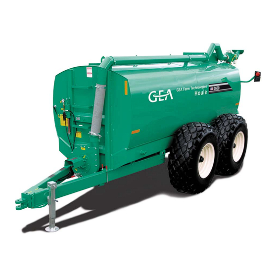
The EL66 tandem liquid manure spreader is designed to be towed by a tractor to carry and spread water or all types of liquid manure. The EL66 tandem liquid manure spreader must not be towed at a speed exceeding 25 mph (40 km/h). -
Page 18: Functional Description
Modifications to the product Functional description The EL66 tandem liquid manure spreader is filled with water or liquid manure through the fill opening (1). The impeller (2) pumps the water/liquid manure in the discharge pipe (3). The water/liquid manure is spreaded through the spreading nozzle (4). -
Page 19: Technical Data
Geometric data (Metric) Technical data Geometric data (SAE & Imperial) The following tables contain approximate values. The type of manure and its composition will significantly increase the total weight, particularly when manure contains sand. EL66 Overall dimension Total weight Load (lbs) (lbs) -
Page 20: Tire Specifications
Technical data Tractor specifications Tire specifications Goodyear 23.1 X 26 Dimensions (inches) Weight (rim included) Diameter Width 23.5 Pressure (psi) Speed (mph) Carrying capacity (lbs) 7554 7980 8512 9044 9510 6930 7320 7808 8296 8723 6305 6660 7104 7548 7937 5680 6000 6400... -
Page 21: Performance Data
Technical data Performance data Performance data Spreader Maximum towing speed 25 mph [40 km/h] Maximum speed using power 8 mph [12 km/h] steering system Operating temperature 5°C [41°F] minimum Spreading flow rate PTO impeller drive Maximum manure consistency for spreading 2 ½”... -
Page 22: Hydraulic Hose Specifications
Technical data Lubricant specifications Hydraulic hose specifications I.D. 1/4” (6 mm) 1/2” (13 mm) 3/4” (19 mm) O.D. 0.58” (15 mm) 0.86” (22 mm) 1.10” (28 mm) Number of braids 5 800 psi 4 000 psi 3 000 psi Service pressure [400 bar] [276 bar] [207 bar]... -
Page 23: Handling And Assembly
Handling and assembly Safety instructions for handling and assembly Handling and assembly Special personnel qualification required for handling Handling must be performed by a qualified forklift operator and/or qualified overhead crane or hoist operator. Read the section Safety - Personnel qualifications. Safety instructions for handling and assembly Warning! Always keep this product on a flat and level surface. -
Page 24: Packing Material Disposal
Handling and assembly Packing material disposal 5.2.1 Handling tools Description Purpose Boom truck To lift the spreader Forklift truck To lift accessories Safety chains To lift accessories 5.2.2 Assembly tools Description Purpose Wrench set To tighten bolts Ratchet tool set To tighten bolts Torque wrench To tighten bolts... -
Page 25: Handling The Product
Warning! Always keep the spreader lifted while laying on the support stands (not supplied by GEA) and make sure the support stands can withstand the spreader weight. ● Position the spreader on support stands (2);... -
Page 26: Hydraulic Braking System Assembly
Handling and assembly Hydraulic braking system assembly Hydraulic braking system assembly 5.5.1 Hub assembly Warning! Do not stand under suspended loads. Falling loads can cause fatal injuries! Attention! To lift wheel hub, use a lifting device with a minimum lifting capacity of 150 lbs [70 kg]. - Page 27 Handling and assembly Hydraulic braking system assembly 5.5.2 Brake parts assembly ● Place the brake pads (1) in the caliper (2) and position the assembly on the brake disk (3); ● Align the holes of the caliper (2) with the holes of the support (4); ●...
-
Page 28: Wheel Assembly
Handling and assembly Anti-siphon assembly Wheel assembly Warning! Do not stand under suspended loads. Falling loads can cause fatal injuries! Attention! To lift the wheels, use a lifting device with a minimum lifting capacity of 1000 lbs [500 kg]. ● Check tire air pressure; ●... -
Page 29: Top Fill Indicator Assembly
Handling and assembly Top fill indicator assembly Top fill indicator assembly Warning! Beware of potential falls: always walk on the nonslip band installed on the product. ● Unscrew both handles (1); ● Remove the top fill indicator (2) from the opening; ●... -
Page 30: Nursing Kit Assembly (Optional)
Handling and assembly Nursing kit assembly (optional) Nursing kit assembly (optional) Warning! Beware of potential falls: always walk on the nonslip band installed on the product. Attention! To lift the nursing kit assembly, use a lifting device with a minimum lifting capacity of 1450 lbs [650 kg]. -
Page 31: Ladder Assembly (Optional)
Handling and assembly Hydraulic door on fill opening assembly (optional) 5.10 Ladder assembly (optional) ● Install the ladder on the spreader using four bolts and locknuts. 5.11 Hydraulic door on fill opening assembly (optional) Warning! Beware of potential falls: always walk on the nonslip band installed on the product. -
Page 32: Hopper Assembly (Optional)
Handling and assembly Rear lights assembly (optional) 5.12 Hopper assembly (optional) Warning! Beware of potential falls: always walk on the nonslip band installed on the product. Attention! To lift the hopper, use a lifting device with a minimum lifting capacity of 125 lbs [50 kg]. -
Page 33: Spreading Nozzles Assembly (Optional)
Handling and assembly Spreading nozzles assembly (optional) 5.14 Spreading nozzles assembly (optional) 5.14.1 Nozzles without manual directional valve Top nozzle assembly ● Place the O-ring (1) around the lid of the adapter (2); ● Place the adapter (2) on the anti-siphon end (3). Bolt the assembly using provided hardware;... - Page 34 Handling and assembly Spreading nozzles assembly (optional) Bottom nozzle assembly Bolted to the spreader ● Place the O-ring (1) around the lid of the adapter (2); ● Place the adapter (2) on the anti-siphon end (3). Bolt the assembly using provided hardware;...
- Page 35 Handling and assembly Spreading nozzles assembly (optional) 5.14.2 Nozzles with manual directional valve Bolted to the spreader Manual directional valve assembly ● Place the O-ring (1) around the lid of the adapter (2); ● Place the adapter (2) on the anti-siphon end (3). Bolt the assembly; ●...
- Page 36 Handling and assembly Spreading nozzles assembly (optional) Bottom nozzle assembly ● Insert the seal (8) inside the vertical tube (9); ● Apply grade 2 PRECISION XL5 MOLY EP2 grease (or equivalent) on the seal (8); ● Slide the vertical tube (9) on the bottom adapter (2) until it reaches the adapter welded ring;...
-
Page 37: Tool Bar Assembly (Optional)
Handling and assembly Tool bar assembly (optional) 5.15 Tool bar assembly (optional) 5.15.1 Tool bar with 24'' hydraulic disc injectors EL54 model shown ● Bolt the tool bar (1) to the spreader frame (2) using provided hardware; ● Fix the support rods (3) to the tool bar (1); EL54 model shown ●... - Page 38 Handling and assembly Tool bar assembly (optional) 5.15.2 Deflectors tool bar EL54 model shown ● Bolt the tool bar (1) to the spreader frame (2) using provided hardware; ● Fix the plate (3) to the hydraulic cylinder (4); ● Install safety chains (5); EL54 model shown ●...
- Page 39 Handling and assembly Tool bar assembly (optional) EL54 model shown ● Install the deflectors (8) on the tool bar (1) using provided hardware; ● Position the hose support (9) halfway between the tool bar end and the hinge (10) on both sides; ●...
- Page 40 Handling and assembly Tool bar assembly (optional) 5.15.3 Flex drop hoses tool bar EL54 model shown ● Bolt the tool bar (1) to the spreader frame (2) using provided hardware; ● Fix the plate (3) to the hydraulic cylinder (4); ●...
- Page 41 Handling and assembly Tool bar assembly (optional) EL54 model shown ● Install the tools (8) on the tool bar (1) using provided hardware; ● Install a hose (9) from the spreader distributor to the tool (8); ● Cut the hose (9) at proper length. The hose (9) should not be tight, keep a loose;...
- Page 42 Handling and assembly Tool bar assembly (optional) 5.15.4 Tool bar with 22'' concave disc incorporators EL54 model shown ● Bolt the tool bar (1) to the spreader frame (2) using provided hardware; ● Connect the hydraulic cylinder to the tool bar (1); ●...
- Page 43 Handling and assembly Tool bar assembly (optional) EL54 model shown ● Install the tools (4) on the tool bar (1); ● Install a hose (5) from the spreader distributor to the tool (4); ● Cut the hose (5) at proper length. The hose (5) should not be tight, keep a loose;...
- Page 44 Handling and assembly Tool bar assembly (optional) 5.15.5 Gauge wheel (if applicable) EL54 model shown ● Fix the gauge wheel on the tool bar as illustrated above using provided hardware; ● To adjust the gauge wheel height, remove the locking plate (1) to unlock the wheel.
- Page 45 Handling and assembly Tool bar assembly (optional) 5.15.6 3 deflectors 38 ft tool bar EL54 model shown ● Apply silicone on flange (2); ● Fix the part (1) to the flange (2) and to the tool bar frame (3), on both sides, using provided hardware;...
- Page 46 Handling and assembly Tool bar assembly (optional) EL54 model shown ● Apply grade 2 PRECISION XL5 MOLY EP2 grease (or equivalent) on the part (5); ● Insert the arm (4) over the part (5); ● Install the pivot support (6) on the arm (4) then fix the pivot support (6) to the tool bar frame (3);...
- Page 47 Handling and assembly Tool bar assembly (optional) EL54 model shown ● Install the deflectors (8) as illustrated above using provided hardware; ● Lubricate all greasing points on the tool bar using grade 2 PRECISION XL5 MOLY EP2 grease (or equivalent); EL54 model shown ●...
-
Page 48: Initial Commissioning
Initial commissioning Safety instructions for initial commissioning Initial commissioning Special personnel qualification required for initial commissioning Initial commissioning must be performed by trained personnel in accordance with the safety instructions. Read the section Safety - Personnel qualifications. Safety instructions for initial commissioning Warning! Do not start this product until the initial commissioning checklist is completed. -
Page 49: Initial Commissioning Checklist
Initial commissioning Initial commissioning checklist Initial commissioning checklist This checklist must be completed by the dealer and the customer to validate that the product is assembled and/or installed according to the manufacturer's instructions and that it is safe for use. Note! Additional information necessary to complete the checklist can be found in this instruction manual. - Page 50 Initial commissioning Initial commissioning checklist Hydraulic brakes DONE The hydraulic brakes are operational. The owner is instructed on how to verify and adjust the master cylinder. The owner is instructed on how to operate the hydraulic braking system. Options DONE The owner is instructed on how to operate the nursing kit.
-
Page 51: Checks After Initial Commissioning
Handing over to the customer Hand over warranty registration form The warranty registration form must be completed and signed by the customer and the dealer. The warranty registration form must be returned to GEA Farm Technologies Canada Inc. to validate the warranty. 2018-9015-005... -
Page 52: Operating
Operating Checks before operation Operating Special personnel qualification required for operation Operation must be performed by qualified personnel in accordance with the safety instructions. Read the section Safety - Personnel qualifications. Safety instructions for operation Warning! Tip over hazard when traveling on a hilly land. Adapt the tractor driving to the land conditions. -
Page 53: Connecting The Spreader
Operating Connecting the spreader Connecting the spreader 7.4.1 Hitching the spreader Attention! Connect the hydraulic hoses properly to ensure safe operation. Refer to section Appendix - Hydraulic diagram. Note! The tractor draw bar must be adjusted to minimum length. Note! The spreader must be towed by the tractor for which it was designed. - Page 54 Operating Connecting the spreader Single / double hitch connection ● Position the tractor to connect its draw bar to the spreader hitch. Double hitch model shown; ● Grease the pin (4) using grade 2 PRECISION XL5 MOLY EP2 grease (or equivalent); ●...
- Page 55 Turn off the tractor and apply the hand brake before connecting or disconnecting the PTO driveline. Refer to the following instructions when the PTO driveline is supplied by GEA otherwise follow the manufacturer's recommendations. Safety chains (European model only) ● Safety chains must be in place at all times to prevent the driveline guards from rotating.
- Page 56 Operating Connecting the spreader Maximum angle of PTO joints Constant velocity PTO driveline 70° 10° maximum maximum ● One PTO joint must be set at a maximum of 70° angle. The other PTO joint must be set at a maximum of 10° angle. 15°...
-
Page 57: Testing Safety Components
Operating Testing safety components Testing safety components Lights ● Check the left and right signal lights and visually confirm their functionality at the rear of the spreader; ● Apply the brake and visually confirm that the brake indicators work properly. Hydraulic braking system ●... -
Page 58: Moving The Spreader
Operating Moving the spreader Moving the spreader Danger! Before moving the spreader on public roads, make sure the tool bar is correctly positioned for safe transportation (set to the smallest position in width, completely raised and locked with safety chains), if applicable. -
Page 59: Loading The Spreader
Operating Loading the spreader Loading the spreader Attention! Make sure all drains and cleaning openings are closed before loading. Attention! Always keep this product on a flat and level surface. Attention! Do not use the jack when the spreader tank contains liquid. Note! Before loading the spreader, make sure that manure is homogenized and that the consistency matches the tool bar capacity. -
Page 60: Spreading
Operating Spreading Spreading Attention! Never open cleaning openings and drains when the spreader tank contains liquid. Attention! If using a PTO, disengage the PTO before turning. Note! Familiarize yourself with the hydraulic functions and spreading tools before spreading. 7.8.1 Spreading with a nozzle ●... - Page 61 Operating Spreading 7.8.3 Spreading with three deflector 38 FT tool bar Danger! Before moving the spreader on public roads, make sure the tool bar is correctly positioned for safe transportation (set to the smallest position in width, completely raised and locked with safety chains), if applicable.
- Page 62 Operating Spreading 7.8.4 Spreading with low spreading tool bar Danger! Before moving the spreader on public roads, make sure the tool bar is correctly positioned for safe transportation (set to the smallest position in width, completely raised and locked with safety chains), if applicable.
- Page 63 Operating Spreading 7.8.5 Spreading with 22” concave disc incorporators Danger! Before moving the spreader on public roads, make sure the tool bar is correctly positioned for safe transportation (set to the smallest position in width, completely raised and locked with safety chains), if applicable.
- Page 64 Operating Spreading 7.8.6 Spreading with 24'' hydraulic disc injectors Danger! Before moving the spreader on public roads, make sure the tool bar is correctly positioned for safe transportation (set to the smallest position in width, completely raised and locked with safety chains), if applicable.
-
Page 65: Operating Spreader Options
Operating Operating spreader options Operating spreader options 7.9.1 In-tank recirculation kit Attention! Disengage the PTO when turning. ● Position directional valve indicator (1) in recirculating mode (2); ● Engage the PTO in low revolution; ● Disengage the PTO to interrupt recirculating mode (example: before turning);... - Page 66 Operating Operating spreader options 7.9.2 Nursing kit Danger! BEWARE OF ELECTRICAL POWER LINES! Operating this product near electrical power lines can result in fatal injuries. Make sure this product is operated in a secure environment. Consult your local electrical supplier regarding electrical safety. Attention! Always keep this product on a flat and level surface.
- Page 67 Operating Operating spreader options 7.9.3 Hydraulic door on fill opening Warning! Do not operate the hydraulic door while a person stands on the spreader. Attention! Make sure the opening is not obstructed. Note! Make sure the ball valve is opened before operating the hydraulic door. The ball valve is located on the door frame.
-
Page 68: Disconnecting
Operating Disconnecting 7.10 Disconnecting PTO driveline disconnection Warning! Turn off the tractor and apply the hand brake before connecting or disconnecting the PTO driveline. Attention! Keep all hose couplings clear of dirt and sand when disconnected. Always hook them on their supports. Note! Refer to the PTO driveline instruction manual and follow the manufacturer's recommendations. - Page 69 Operating Disconnecting ● If using a hydraulic jack (4), connect the hydraulic hoses to the tractor to extend the jack; ● Remove the safety chains (5) from the tractor; Single / double hitch ● Remove the pin (6); ● Using the jack, lift the spreader draw bar.
-
Page 70: Troubleshooting
Troubleshooting Troubleshooting possible faults Troubleshooting Special personnel qualification required for troubleshooting Troubleshooting must be performed by trained personnel in accordance with the safety instructions. Read the section Safety - Personnel qualifications. Safety instructions for troubleshooting Read the section Safety. Troubleshooting possible faults Spreading Symptom Possible cause... - Page 71 Troubleshooting Troubleshooting possible faults Hydraulic braking system Symptom Possible cause Solution The spreader partially The hydraulic hoses of the Connect hydraulic hoses brakes or does not brake at tractor are not connected to properly. Refer to section all. the hydraulic braking Appendix - Hydraulic system.
- Page 72 Troubleshooting Troubleshooting possible faults Electrical Symptom Possible cause Solution Signal lights / Halogen Electrical plug is not Connect electrical plug to lights do not turn on. connected to the tractor. the tractor. Light bulb burned out. Replace light bulb. Electrical wires cut. Repair the electrical problem.
-
Page 73: Maintenance
Maintenance Safety instructions for maintenance Maintenance Special personnel qualification required for maintenance work Maintenance work must be performed by trained personnel in accordance with the safety instructions. Read the section Safety - Personnel qualifications. Safety instructions for maintenance Attention! Tractor PTO or hydraulic components must be disconnected unless otherwise specified in the maintenance instructions. -
Page 74: Schedule Maintenance Responsibilities
Calibrate the hydraulic braking system Attention! When operating this GEA product using other manufacturers components and/or products such as a PTO, a tractor, a motor, a pump, etc., ALWAYS perform maintenance of the component and/or product as recommended by its manufacturer. -
Page 75: Visual Inspection
Maintenance Lubricate hitch Visual inspection Before each use Inspect the spreader to find any defective parts or signs of abnormal wear. Lubricate hitch Before each use or every 10 hours Note! Use grade 2 PRECISION XL5 MOLY EP2 grease (or equivalent). Single / double hitch ●... -
Page 76: Lubricate The Equipment
Maintenance Fill the grease chamber of the bearing housing Lubricate the equipment Before each use or every 10 hours Note! Use grade 2 PRECISION XL5 MOLY EP2 grease (or equivalent). ● Lubricate all parts labelled with: Refer to section Appendix - Label position. Check oil level of bearing housing Before each use or every 10 hours Note! -
Page 77: Torque Wheel Nuts
Maintenance Grease wheel hub bearings Torque wheel nuts Before each use or every 10 hours Note! It is of prime importance to check the torque of the nuts after the 3 to 5 first trips. ● Ensure wheel nuts are torqued to 375 ft-lb [508 NM];... -
Page 78: Torque Bolts
Maintenance Lubricate the tool bar (option) 9.11 Torque bolts Every 200 hours of use Check torque of: ● transportation support bolts; ● components fastened on the spreader. Refer to section Technical data - Bolt torque chart. 9.12 Change the oil of bearing housing Every 200 hours of use Note! Use 80W-90 TRAXON... -
Page 79: Open Drains
Maintenance Open drains 9.14 Open drains After each use Attention! Make sure the spreader is empty before opening the drains. ● Use the wheel nut wrench to turn the pivot bolt (1) to open the drain (2); ● Clean the drain (2); ●... -
Page 80: Open Cleaning Openings
Maintenance Open cleaning openings 9.15 Open cleaning openings After each use Attention! Make sure the spreader is empty before opening cleaning openings. ● Unscrew the handles (1); ● Remove the cover. 2018-9015-005 80 / 118 09-2016... -
Page 81: Clean The Product
Maintenance Clean the product 9.16 Clean the product After each use and once a year Warning! Beware of potential falls: always walk on the nonslip band installed on the product. Attention! Use cold water to clean this product. Do not exceed 2000 psi [105 bar] when using a pressure washer and keep the nozzle at a distance of 1ft [30 cm] from the surface to clean. -
Page 82: Change Hydraulic Brake Parts
Maintenance Change hydraulic brake parts 9.17 Change hydraulic brake parts If necessary Remove the wheel Attention! Make sure the spreader is empty. ● Using a jack with a minimum lifting capacity of 4000 lbs (2000 kg), lift the spreader wheel; ●... - Page 83 Maintenance Change hydraulic brake parts Remove calipers ● Remove bolts (1) and sleeves (2) from the calipers (3); ● Remove the calipers (3) from the brake disk (4); ● Remove the brake pads (5) from the calipers (3); ● Replace the brake pads (5); ●...
-
Page 84: Calibrate The Hydraulic Braking System
Maintenance Calibrate the hydraulic braking system 9.18 Calibrate the hydraulic braking system If necessary Bleed brake system Note! Use DOT 3 brake fluid. ● Connect the hydraulic hoses of the spreader braking system to the tractor; ● Start the engine of the tractor; ●... -
Page 85: Shear Bolts Replacement Kit
Maintenance Shear bolts replacement kit Adjust master cylinder Note! Use DOT 3 brake fluid. ● Connect the hydraulic hoses of the tractor to the spreader braking system; ● Start the engine of the tractor; ● Do not apply the brakes. Measure the length of the master cylinder rod (1);... -
Page 86: Decommissioning
Decommissioning Safety instructions for decommissioning Decommissioning 10.1 Special personnel qualification required for decommissioning Decommissioning may only be performed by qualified personnel in accordance with the safety instructions. Read the section Safety - Personnel qualifications. 10.2 Safety instructions for decommissioning Attention! Keep all hose couplings clear of dirt and sand when disconnected from the tractor. -
Page 87: Temporary Decommissioning
Decommissioning Temporary decommissioning 10.3 Temporary decommissioning Cleaning Warning! Beware of potential falls: always walk on the nonslip band installed on the product. Attention! Use cold water to clean this product. Do not exceed 2000 psi [105 bar] when using a pressure washer and keep the nozzle at a distance of 1 ft [30 cm] from the surface to clean. -
Page 88: Final Decommissioning/Disposal
Decommissioning Final decommissioning/disposal Lubricate ● Grease parts labelled with: ● Spray the entire product with a thin layer of biodegradable oil to protect from corrosion. Refer to section Appendix - Label position. Store Note! Refer to the PTO driveline instruction manual and follow the manufacturer's recommendations. -
Page 89: Appendix
Appendix Label position Appendix 11.1 Label position 11.1.1 Safety labels 2018-9015-005 89 / 118 09-2016... - Page 90 Appendix Label position 2099-4721-050 2099-4721-080 2099-4720-100 2010-4701-590 2099-4720-020 2099-4721-020 2007-4700-390 2010-4703-430 2010-4703-440 2099-4722-040 2018-4701-840 2018-9015-005 90 / 118 09-2016...
- Page 91 Appendix Label position 11.1.2 Lubrication labels 2099-4701-240 2099-4701-250 2018-9015-005 91 / 118 09-2016...
-
Page 92: Hydraulic Diagrams
Appendix Hydraulic diagrams 11.2 Hydraulic diagrams 11.2.1 EL66 hydraulic brake supplied only for manually activated brakes Legend: Disk brakes Master cylinder Calipers Pressure gauge 2018-9015-005 92 / 118 09-2016... - Page 93 Appendix Hydraulic diagrams 11.2.2 Solenoid valves control option Legend: Solenoid valve Hydraulic component #2 Selector switch Tractor hydraulic outlets Hydraulic component #1 Tractor electric connection (12VDC) 2018-9015-005 93 / 118 09-2016...
- Page 94 Appendix Hydraulic diagrams 11.2.3 Nursing kit option Legend: Hydraulic cylinder Hydraulic motor Optional hydraulic cylinder Restrictor 2018-9015-005 94 / 118 09-2016...
-
Page 95: Hydraulic Diagrams - Flex Drop Hoses Or Low Pressure Deflectors
Appendix Hydraulic Diagrams - Flex drop hoses or Low pressure deflectors 11.3 Hydraulic Diagrams - Flex drop hoses or Low pressure deflectors 11.3.1 Flex Drop Hoses or Low Pressure Deflectors (with Folding Ends) Legend: Tool bar hydraulic cylinder Ball valve Folding end hydraulic cylinder Restrictor Pressure... - Page 96 Appendix Hydraulic Diagrams - Flex drop hoses or Low pressure deflectors 11.3.2 Flex Drop Hoses or Low Pressure Deflectors (with Folding Ends and Hydraulic Shredder) Legend: Tool bar hydraulic cylinder Ball valve Folding end hydraulic cylinder Restrictor Shredder hydraulic motor Pressure relief valve Pressure Tank...
- Page 97 Appendix Hydraulic Diagrams - Flex drop hoses or Low pressure deflectors 11.3.3 Flex Drop Hoses or Low Pressure Deflectors (with Folding Ends and Recirculation Kit) Legend: Tool bar hydraulic cylinder Ball valve Folding end hydraulic cylinder Restrictor Recirculation valve hydraulic cylinder Pressure Tank 2018-9015-005...
- Page 98 Appendix Hydraulic Diagrams - Flex drop hoses or Low pressure deflectors 11.3.4 Flex Drop Hoses or Low Pressure Deflectors (with Folding Ends, Recirculation Kit and Hydraulic Shredder) Legend: Tool bar hydraulic cylinder Ball valve Folding end hydraulic cylinder Restrictor Shredder hydraulic motor Pressure relief valve Recirculation valve hydraulic cylinder Pressure...
-
Page 99: Hydraulic Diagrams - 22" Concave Disc Incorporators
Appendix Hydraulic Diagrams - 22” Concave disc incorporators 11.4 Hydraulic Diagrams - 22” Concave disc incorporators 11.4.1 22” Concave disc incorporators without folding ends Legend: Tool bar hydraulic cylinder Restrictor Recirculation valve hydraulic cylinder Ball valve (included with recirculation kit) Shredder hydraulic motor Relief valve kit for pressurized tool bar (optional) - Page 100 Appendix Hydraulic Diagrams - 22” Concave disc incorporators 11.4.2 22” Concave disc incorporators with folding ends Legend: Tool bar hydraulic cylinder Restrictor Folding end hydraulic cylinder Ball valve Shredder hydraulic motor Ball valve (included with recirculation kit) Recirculation valve hydraulic cylinder Relief valve kit for pressurized tool bar (optional) Pressure relief valve...
-
Page 101: Hydraulic Diagrams - 24" Hydraulic Disc Injectors
Appendix Hydraulic Diagrams - 24” Hydraulic Disc Injectors 11.5 Hydraulic Diagrams - 24” Hydraulic Disc Injectors 11.5.1 24” Hydraulic Disc Injectors (6 Injectors without tool bar cylinders) Legend: Disc hydraulic cylinder Restrictor Shredder hydraulic motor (optional) Ball valve (included with recirculation kit) Recirculation valve hydraulic cylinder Pressure gauge (optional) - Page 102 Appendix Hydraulic Diagrams - 24” Hydraulic Disc Injectors 11.5.2 24” Hydraulic Disc Injectors (6 Injectors with tool bar cylinders) Legend: Disc hydraulic cylinder Ball valve (included with recirculation kit) Tool bar hydraulic cylinder Pressure gauge Shredder hydraulic motor (optional) Pressure relief valve Recirculation valve hydraulic cylinder Relief valve kit for pressurized tool bar (optional)
- Page 103 Appendix Hydraulic Diagrams - 24” Hydraulic Disc Injectors 11.5.3 24” Hydraulic Disc Injectors (8 Injectors without tool bar cylinders) Legend: Disc hydraulic cylinder Restrictor Shredder hydraulic motor (optional) Ball valve (included with recirculation kit) Recirculation valve hydraulic cylinder Pressure gauge (optional) Pressure relief valve Needle valve...
- Page 104 Appendix Hydraulic Diagrams - 24” Hydraulic Disc Injectors 11.5.4 24” Hydraulic Disc Injectors (8 Injectors with tool bar cylinders) Legend: Disc hydraulic cylinder Ball valve (included with recirculation kit) Tool bar hydraulic cylinder Pressure gauge Shredder hydraulic motor (optional) Pressure relief valve Recirculation valve hydraulic cylinder Needle valve (optional)
-
Page 105: Hydraulic Diagram - Dmi Or Yetter Injectors
Appendix Hydraulic Diagram - DMI or Yetter Injectors 11.6 Hydraulic Diagram - DMI or Yetter Injectors Legend: Tool bar hydraulic cylinder Restrictor Shredder hydraulic motor (optional) Ball valve (included with recirculation kit) Recirculation valve hydraulic cylinder Relief valve kit for pressurized tool bar (optional) (optional) Pressure relief valve... -
Page 106: Hydraulic Diagram - 7 Dmi Injectors
Appendix Hydraulic diagram - 7 DMI Injectors 11.7 Hydraulic diagram - 7 DMI Injectors Legend: Tool bar hydraulic cylinder Restrictor Shredder hydraulic motor (optional) Ball valve (included with recirculation kit) Recirculation valve hydraulic cylinder Relief valve kit for pressurized tool bar (optional) (optional) Pressure relief valve... -
Page 107: Hydraulic Diagram - Bourgeault Disc Injectors
Appendix Hydraulic Diagram - Bourgeault Disc Injectors 11.8 Hydraulic Diagram - Bourgeault Disc Injectors Legend: Tool bar hydraulic cylinder Restrictor Shredder hydraulic motor (optional) Ball valve (included with recirculation kit) Recirculation valve hydraulic cylinder Relief valve kit for pressurized tool bar (optional) (optional) Pressure relief valve... -
Page 108: Hydraulic Diagram - 38 Ft Wide Tool Bar With 3 Deflectors
Appendix Hydraulic diagram - 38 FT Wide Tool Bar with 3 Deflectors 11.9 Hydraulic diagram - 38 FT Wide Tool Bar with 3 Deflectors Legend: Tool bar hydraulic cylinder Pressure relief valve Folding arm hydraulic motor (left side) Restrictor Folding arm hydraulic motor (right side) Ball valve Pressure Tank... -
Page 109: Electric Diagram
Appendix Electric diagram 11.10 Electric diagram 11.10.1 Signal lights Left side Right side Auxiliary lights Legend: White (W) Ground Black (Bl) Auxiliary lights Yellow (Y) Left flasher Red (R) Brakes Green (G) Right flasher Brown (Br) Parking light Not used 2018-9015-005 109 / 118 09-2016... -
Page 110: Consistency Test
11.11 Consistency test GEA Houle determined the following method to verify if the viscosity of the liquid manure is suitable for this product. 1. Set a pail on a level surface and install a 24” [60cm] round plate at the center of the pail. -
Page 111: Spreading Rate Calculation
Appendix Spreading rate calculation 11.12 Spreading rate calculation Four parameters are needed to determine a spreading rate: the volume of manure, the time needed to spread the manure, the tractor speed and the spreading width. Determine which type of measurement unit (imperial or metric) and follow the instructions. - Page 112 Appendix Spreading rate calculation Flow rate formula: Metric unit Spreader volume ÷ spreading time = litres/minute Example: 14550 litres ÷ 3 minutes = 4850 litres/minute Imperial unit Spreader volume ÷ spreading time = gal (UK)/minute Example: 3200 gal (UK) ÷ 3 minutes = 1067 gal (UK)/min Spreading rate formula: Metric unit Flow rate x 600 ÷...
-
Page 113: Flow Rate Adjustment
Appendix Flow rate adjustment 11.13 Flow rate adjustment The spreading rate takes the flow rate into account; If the flow rate is reduced, the spreading rate is proportionally reduced; When the maximum spreading speed is reached and the spreading rate is too high for the needs and as per the local regulations, flow rate must be reduced;... - Page 114 Appendix Flow rate adjustment Step 2: Flow regulator (if applicable) A spreader can be equipped with a spreading tool bar using a distributor to provide an equal amount of manure to each spreading nozzle. The flow regulator connected to the distributor is used to direct liquid manure inside the spreader tank therefore limiting the amount of manure inside the distributor.
- Page 115 Appendix Flow rate adjustment Step 3: Restriction plate (if applicable) A spreader discharge pipe can be equipped with a housing designed to insert a restriction plate to limit flow rate. ● Slide a restriction plate (1) in the housing (2); ●...
- Page 116 Appendix Flow rate adjustment Step 5: Deflector restrictor (if applicable) When using a tool bar to spread manure, a restrictor is inserted in each deflector to limit the opening and to reduce the flow rate. Pressure is increased to allow larger spreading width. ●...
-
Page 117: Abbreviations
Appendix Abbreviations 11.14 Abbreviations Terms Explanation Terms Explanation Ø diameter European Community clockwise counterclockwise facsimile I.D. inside diameter Inc. Incorporated national coarse O.D. outside diameter power take off polyvinyl chloride Society Automotive Quebec Engineers United States of America World Wide Web Units Explanation Units... - Page 118 Excellence • Passion • Integrity • Responsibility • GEA-versity GEA Group is a global engineering company with multi-billion euro sales and operations in more than 50 countries. Founded in 1881, the company is one of the largest providers of innovative equipment and process technology.
Need help?
Do you have a question about the EL66 and is the answer not in the manual?
Questions and answers