
Related Manuals for ontrac Easytrac EME50


Summary of Contents for ontrac Easytrac EME50
- Page 1 Easytrac EME/EOE Electric Actuator Operation Instruction (for actuators with software release V1.27) Ontracactuators.com ACK23-01A...
-
Page 2: Table Of Contents
CONTENTS 1. Device Identification 1.1 Actuator ID Label ..........................1 1.2 Legend ..............................1 2. General 2.1 Application ............................3 2.1.1 Purpose of the Manual ........................3 2.1.2 Qualification and Training of the Personnel .................. 3 2.1.3 Explosive Atmosphere Zones ....................... 3 2.2 Safety Advice ............................ - Page 3 5.4 Key Features ............................. 15 5.5 Partial Stroke Test (PST) ........................15 5.6 Position Sensing ..........................16 5.7 Sensitivity Control ..........................16 5.8 Remote Controller ..........................17 5.9 Serial Communication ........................17 5.10 Smartrac for Asset Management ..................... 17 5.11 QR Code ............................18 5.12 Actuator Protection ..........................
- Page 4 8.3 Operation Menu ..........................34 9. Alarms and Failures 9.1 Alarm and Failure Messages ......................37 10. Product Maintenance 10.1 General ............................37 11. Service……………………………………………………………………………………………………...…….37 ACK23-01A ontracactuators.com...
-
Page 5: Device Identification
Year Torque= Speed= Output flange= Signal= Pmax= Imax= Temp= IP67 Made by Ontrac line 1: actuator Type line 2: serial no. / year of construction line 3: max. switch-off torque /max. output speed line 4: output flange / input/output signal... - Page 6 We remind the installer that the classification of the zone (REF. ATEX 2014/34/EU former 94/9/CE directive) for potentially explosive atmosphere zones has to be done by the operator of the actuator and communicated to Ontrac and/or approved agent for the right choice of classification of the equipment to work in these zones.
-
Page 7: General
EX-Proof Version. We remind you that the classification of the zone (REF. ATEX 2014/34/EU former 94/9/CE directive) for potentially explosive atmosphere zones has to be done by the customer and communicated to Ontrac for the right choice of the kind of actuator suitable to work in these zones. ACK23-01A... -
Page 8: Safety Advice
2.2 Safety Advice Preliminary remarks All the references to the manual have to be considered applicable also to environment and system that use these actuators unless it's specified otherwise. 2.2.1 Introduction ATTENTION: the non-observance of the indications stated in this manual or the inappropriate use of the equipment by unqualified or unauthorized staff, can cause serious personal injuries or death and damage to the equipment! The technical assistance office is at complete disposal;... -
Page 9: Other Safety Advices
8. The main power supply may be supplied as three phases or single phase voltage. Please apply caution when wiring. 9. Before commissioning, check whether all settings meet the requirements. Incorrect settings may be dangerous. 10. Consult the vendor of the equipment or Ontrac before making any physical changes to the equipment. ACK23-01A ontracactuators.com... -
Page 10: Receiving And Storage
The use outside these specifications has to be agreed and approved by Ontrac. It must be considered also that, if the actuators are used outside their technical specifications, the factory warranty are no longer valid. -
Page 11: Storage
The actuator has to be used only for the applications specified in the order for which Ontrac has selected the model, the materials of construction and has tested the actuator to respect the specifications. For other uses different from those stated in the order, the customer has to send always a written request to the Ontrac technical office, which on its part will reply in a written form. -
Page 12: Main Components
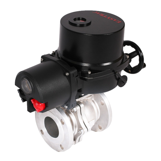
4. Main Components 4.1 Name of Each Component 1. Upper cover for motor & wiring connections compartment 2. Control panel 3. Gearcase 4. Connecting flange 5. Removable valve adaptor 6. Manual switch handle 7. Handwheel 8. Integral electrical control unit 9. -
Page 13: Flange Structure And Valve Connection Size
4.2 Flange Structure and Valve Connection Size Parallel to handwheel axis Code Flange Standard Factory Factory Maximum Model size default default allowed □11 EOE/EME50 Ø100 Ø50 Ø50 Ø8 Ø26 4-M6 deep 9 4-M8 deep Ø70 Ø70 EOE/EME100 □14 Ø126 Ø10 Ø38 EOE/EME200 4-M10 deep... -
Page 14: General And Technical Data10
5. General and Technical Data 5.1 Technical Data EOE/EME Intelligent Type Basic Type (On/Off Only) (with control unit) Part-turn Linear Output Torque/Thrust 50-1000 Nm 50-1000 Nm 0~4000N/0~6000N Whole Stroke Time 22-65 s 22-87 s 45s at 50mm (Speed: 0.9mm/s) Power Supply 3 phase 380VAC 50 HZ (±5%) 3 phase 380VAC 50 HZ (±5%) 3 phase 380VAC 50 HZ (±5%) -
Page 15: Model And Weight
Operation Mode: Hold-to run: actuator moves as long as an external or push button command exists. • Digital Input(DI1 ... DI5): • Analogue input(AI): 4~20mA, input impendence 250 Ω, rise 4 optocoupler, active port, freely configurable; • Digital Output(DO1 ... DO4): characteristics •... -
Page 16: Easytrac Intelligent Type Outline Dimension Drawings (Part-Turn)
K direction Crank arm, 0-360° adjustable Base and Lever EOE800/1000: K direction Crank arm, 0-360° adjustable Base and Lever 5.3.2 Easytrac Intelligent Type Outline Dimension Drawings (PART-TURN) Direct mounting Base and lever Φ D Model Torque Open/ Power Close Flange Weight Weight ENISO... - Page 17 EOE50/100/200/400/600: K direction Crank arm, 0-360° adjustable Base and Lever EME50/100/200/400/600: K direction Crank arm, 0-360° adjustable Base and Lever ACK23-01A ontracactuators.com...
-
Page 18: Easytrac Intelligent Type Outline Dimension Drawings (Linear)
5.3.3 Easytrac Intelligent Type Outline Dimension Drawings (Linear) Modulating Speed Max. Stroke Model Thrust Power Flange Weight Thrust mm/s EME400-L 4000N 2000N 84.5 F05、F07 10Kg EOE400-L EME600-L 6000N 3000N 84.5 F05、F07 11Kg EOE600-L Stem Connection Size: M10x1、M10x1.25、M10x1.5 M12x1、M12x1.25、M12x1.5 M14x1、M14x1.25、M14x1.5 Flange Connection: F05、F07 M16x1、M16x1.25、M16x1.5 5.3.4 Easytrac Split Type Outline Dimension Drawings ACK23-01A... -
Page 19: Key Features
5.4 Key Features ● For Intelligent Model (With control unit): Password protection Auto phase correction, Phase lost detection Input/output user programable Reverse protection Jam valve/Blockage, 1.5 torque of nominal max torque Absolute encoder for sensing with high Resolution ... -
Page 20: Position Sensing
To achieve a successful PST, the following terms must be met: 1. The actuator must be in the open or close position. The starting position of the travel test is 0-100% PST. This value must be 0% or 100%. If the actuator is not in this position when PST starts, the test will not be executed and will not successfully end. -
Page 21: Remote Controller
5.8 Remote Controller User friend local menu operation With infra red communication, recommend to use within 1m from actuator Only for general purpose use 5.9 Serial Communication Profibus: Profibus DP (Decentralized Peripherals) up to a baud rate of 1.5Mbit/s. Our actuators are supplied with active bus termination. -
Page 22: Qr Code
Manufacturing data authentication Service request linked to Ontrac website 5.12 Actuator Protection Easytrac provides an option for double sealing for Explosion proof, or IP68 version, for even more protection against ingress. Two seals are provided which gives additional protection when the actuator terminal compartment is open. -
Page 23: Cable Entries
Double Seal 5.13 Cable Entries For standard Easytrac, we offer 2 entries, 1xM25 for power supply, 1x M25 for signals in/out and serial communication. (Refer to Fig1) For Ex type of Easytrac, we offer 4 entries, 1xM25 and 1xM32 for power supply, 2x M16 for signals in/out and serial communication or bus routing. -
Page 24: Installation
- Does the actuator fit to the valve? Fitting to a valve: Ontrac actuator are supplied in closed position. The units are standard configured to give clockwise output on a close command. The Handwheel can be supplied to give clockwise or anticlockwise output, this needs to be verified at ordering stage, it can not easily be changed on site! ... -
Page 25: Hand Crank Force
6.3 Hand Crank Force A hand crank with lever is provided for manual operation. Exceeding the permissible hand crank force, required for the max.on-off torque, can damage the actuator and / or the valve. The following hand crank forces are required to provide the max. on-off torque: Reduction ratio for part turn: •... -
Page 26: Stop Bolts
Reduction ratio for linear: • For EOE/EME 400L, 4000/4/35≈28.6Nm That is the force received at a distance of 1m is 28.6N. Because the diameter of the hand crank is 0.1M, the force received on the hand crank is 286N • For EOE/EME 600L, 6000/4/35≈42.9Nm That is the force received at a distance of 1m is 42.9N. - Page 27 Installation procedure: 1. Make sure the installation space and platform are proper for actuator. The size of actuator and its base, please to refer fig. 1 For indications to the holes in the base flange, refer to the following illustration. Fig.1 Fig.2 2.
- Page 28 4. Installation of Damp Rod (Provided by Customer) The following table shows the dimensions Fig.4 Selection and dimension table of ball joint Adjust parameters Inner diameter and Diameter Hinge Screw Maximum Minimum wall thickness of of direct Adjustment torque length thread adjustment adjustment...
-
Page 29: Electrical Connection
7. Electrical Connection 7.1 Electrical Wiring Diagram 7.1.1 Wiring Diagrams of Intelligent Mode (with Control Unit): 3-phase AC,380V(on-off) 3-phase AC,380V(Modulating duty) 3-phase AC,380V(on-off) 1-phase AC,220V(Modulating duty) 1-phase AC,220V(on-off) 1-phase AC,220V(on-off) Default Setting(DO) Default Setting(DI) Function Output channel Function Input channel Full open indication Open direction Full close indication... -
Page 30: Wiring Diagrams Of Base Mode
7.1.2 Wiring Diagrams of Base Mode: 1-phase AC, 110V/220V 3-phase AC, 380V 7.1.3 Wiring Diagrams of Split-Type: 1. The sensor signal cable shall be 14-core cable with shield; The sectional area of the line shall be 0.5mm², and the length of the line shall not exceed 5m; 2. -
Page 31: Wiring Diagrams Of Additional Channel (Control B)
7.1.4 Wiring Diagrams of Additional Channel (Control B): 3-phase AC,380V(Modulating duty) 3-phase AC,380V(on-off) Default Setting(DI) Function Input channel Open direction Close direction Stop direction ESD direction Set point enable Alarm reset 1-phase AC,220V(Modulating duty) 1-phase AC,220V(on-off) Default Setting(DO) Function Output channel Full open indication Full close indication Remote indication... -
Page 32: Profibus Dp Wiring Diagram
7.1.5 Profibus DP Wiring Diagram: Ontrac electric actuators can support Profibus- DP fieldbus protocol with additional code of "286". A Profibus network segment can connect up to 32 Ontrac electric actuators. The transmission speed of Ontrac electric actuators can be 9.6kbps ~ 1500kbps... -
Page 33: Modbus Wiring Diagram
7.1.6 Modbus Wiring Diagram: Ontrac electric actuators can support Modbus protocol with additional code of "288". ACK23-01A ontracactuators.com... -
Page 34: Wiring Steps
7.2 Wiring Steps 7.2.1 Electrical Wiring: 1. Use an Allen wrench remove the top cover of actuator. 2. Thread wiring cable through the waterproof connectors, for plug-in end cover, remove connector before wiring, and restore it after wiring. 3. Tighten waterproof screw to seal all the cable entrance. 4. -
Page 35: Wiring Installation Of Bus Board (For Option)
7.2.2 Wiring Installation of Bus Board (for option): Please use a system of personal earthing to avoid damage to the boards by electric sparks 3. Use three combination cross 2. Thread the cross pan heads 1. Use an Allen wrench pan head screws (M4x8) to crew X3 (m3x16) through the to remove the Allen... -
Page 36: Anti-Condensation Heater
7.3 Anti-condensation heater Switch-on the mains supply in order to avoid condensation 7.4 Wire cross section (plug) Power cable 1.5 mm (inflexible or flexible) Signal cable 0.75 mm (inflexible or flexible) 7.5 Thread size for cable glands Metric (Standard) 2xM25x1.5 Terminals 1xM25x1.5、1xM32x1.5、2xM16x1.5 Terminals... -
Page 37: Adjustment
8. Adjustment 8.1 Mode Selector Switch Instruction The actuator is equipped with a local control panel with various elements for operation and display. Switch the mode selector switch to LOCAL in order to drive the actuator with the operating switch open/close. for parameter setting via local control panel. - Page 38 8.3 Operation Menu Main Menu Structure Almost all of actuators' function can be adjusted (position setting, parameter setting, configuration, diagnosis, etc.) via control panel. Submenu Structure ACK23-01A ontracactuators.com...
- Page 39 ACK23-01A ontracactuators.com...
- Page 40 (Note: 6.3 &6.4 for option.) ACK23-01A ontracactuators.com...
- Page 41 If required, tighten the screws. Every 2 years, check each actuator visually for leakage of oil/grease. 11. Service • Ontrac and its partners provides comprehensive services upon request. Please visit us at www.ontracactuators.com ACK23-01A ontracactuators.com...
- Page 42 Copyright©2023 Ontrac instrument. All rights reserved Subject to technical changes. This technical documentation is protected by copyright law. Do not translate, copy or distribute in any way even in a modified form or as an excerpt without the prior written permission of the right holder. Also, reprints, photomechanical or electronical reproduction or storage of data in data processing systems or data networks must be authorized by the right-holder.
Need help?
Do you have a question about the Easytrac EME50 and is the answer not in the manual?
Questions and answers