
Related Manuals for Dover PSG ALL-FLO A300


Summary of Contents for Dover PSG ALL-FLO A300
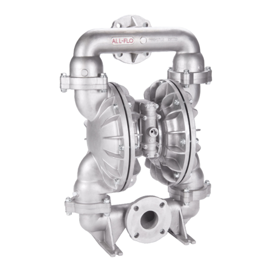
- Page 1 INSTALLATION OPERATION & MAINTENANCE A300 METAL 3 INCH AIR-OPERATED DOUBLE-DIAPHRAGM PUMP...
-
Page 2: Table Of Contents
TABLE OF CONTENTS SECTION 1 WARNINGS, DANGERS AND CAUTIONS SECTION 2 MODEL DESIGNATION MATRIX & REPAIR KITS SECTION 3 PRINCIPLES OF OPERATION SECTION 4 DIMENSIONAL DRAWINGS SECTION 5 PERFORMANCE CURVES RUBBER DIAPHRAGMS ..........9 TPE DIAPHRAGMS ............9 PTFE DIAPHRAGMS ..........9 SECTION 6 INSTALLATION INSTALLATION............ -
Page 3: Warnings, Dangers And Cautions
SECTION CAUTIONS — READ FIRST! READ THESE WARNINGS AND SAFETY PRECAUTIONS PRIOR = Hazards or unsafe practices WARNING TO INSTALLATION OR OPERATION. FAILURE TO COMPLY which could result in severe WITH THESE INSTRUCTIONS COULD RESULT IN PERSONAL personal injury, death or INJURY AND OR PROPERTY DAMAGE. -
Page 4: Model Designation Matrix & Repair Kits
SECTION MODEL DESIGNATION MATRIX & REPAIR KITS - ALUMINUM FLUID CONNECTION TYPE SPECIAL OPTION VALVE SEAT (HARDWARE, MUFFLER, LUG) N = NPT E = EPDM (Integral Valve & O-Ring) B = BSPT N = Buna-N (Integral Valve & O-Ring) 3 = Default (Zinc Plated Hardware, Plastic Muffler) 4 = Zinc Plated Steel Hardware, Premium Muffler Y = Nylon AIR SECTION... - Page 5 MODEL DESIGNATION MATRIX & REPAIR KITS - STAINLESS STEEL SPECIAL OPTION (HARDWARE, FLUID CONNECTION TYPE VALVE SEAT MUFFLER, LUG) F = ANSI/DIN FLANGE E = EPDM (Integral Valve & O-Ring) 7 = Default (Stainless Steel Hardware, Plastic N = Buna-N (Integral Valve & O-Ring) Muffler) 3 = Stainless Steel AIR SECTION...
-
Page 6: Principles Of Operation
SECTION PRINCIPLES OF OPERATION HOW AN AIR OPERATED DOUBLE DIAPHRAGM PUMP WORKS The air-valve directs pressurized air behind the diaphragm on the right, causing the diaphragm on the right to move outward (to the right). Since both the right diaphragm and the left diaphragm are connected via a diaphragm rod, when the right diaphragm moves to the right, the left diaphragm (through the action of the diaphragm rod) moves to the right also. -
Page 7: Dimensional Drawings
SECTION 3” PUMP DIMENSIONS ALUMINUM - THREADED 3.3" (84mm) 3.3" (84mm) 3.3" (84mm) 32.6" (827mm) 30.2" (767mm) 3/4”-14 FNPT (Air Inlet) 32.6" (827mm) 32.6" (827mm) 30.2" (767mm) 30.2" (767mm) 16.5" (420mm) 16.5" (420mm) 16.5" (420mm) 2.5" (64mm) 12.4" (315mm) 2.5" (64mm) 2.5"... - Page 8 3” PUMP DIMENSIONS STAINLESS STEEL - FLANGED 3.6" (90mm) 3.6" (90mm) 3.6" (90mm) 3/4”-14 FNPT (Air Inlet) 35.2" (893mm) 35.2" (893mm) 35.2" (893mm) 31.4" (798mm) 31.4" (798mm) 31.4" (798mm) 18.2" (463mm) 18.2" (463mm) 18.2" (463mm) 4.2" (106mm) 4.2" (106mm) 4.2" (106mm) 12.4"...
-
Page 9: Performance Curves
SECTION PERFORMANCE CURVES PERFORMANCE CURVE (3” RUBBER)* Performance Specifications Max. Flow: 235 gpm (890 lpm) Max. Air Pressure: 120 psi (8.3 bar) AIR CONSUMPTION (SCFM) Max. Solids: 7/16” (11 mm) Max. Suction Lift Dry: 20 ft-H O (6.1 m-H Max. Suction Lift Wet: 31 ft-H O (9.4 m-H Weight:... -
Page 10: Installation
SECTION INSTALLATION, TROUBLESHOOTING AND MAINTENANCE INSTALLATION Ensure that the air supply is sufficient for the PIPING volume of air required by the pump. Refer to product specifications for further details. For reliable Whenever possible ensure the pump is installed using operation, install a 5 micron air filter, air-valve and the shortest possible pipe lengths with the minimum pressure regulator. - Page 11 SECTION SUGGESTED INSTALLATION This illustration is a generic representation of an air operated double-diaphragm pump. ALF-12090-E-01 All-Flo...
-
Page 12: Troubleshooting
SECTION TROUBLESHOOTING PROBLEM EFFECT/SOLUTION Pump Will Not Cycle Discharge line closed or plugged Discharge filter blocked Check valve stuck Air filter blocked Air supply valve closed Air supply hooked up to muffler side of pump Compressor not producing air or turned off Muffler iced or blinded Diaphragm ruptured Plant air supply line ruptured... -
Page 13: Operation
OPERATION MAINTENANCE The Air-Operated Double Diaphragm Pump requires Due to the unique nature of each application, periodic a minimum of 20 psig of air to operate, with some inspection of the pump is the best method to determine variation according to diaphragm material. Increasing a proper maintenance schedule. -
Page 14: Repair And Assembly
SECTION REPAIR AND ASSEMBLY PUMP WET END REMOVAL TOOLS NEEDED WARNING Prior to servicing the pump, ensure that the air and 1) Two Wrenches, 3/4 Inch fluid lines are closed and disconnected. While wearing personal 2) Two Adjustable Wrenches or Vice protective equipment, flush, drain and process liquid from the pump in a safe manner. - Page 15 SECTION STEP 7 STEP 8 STEP 9 In order to remove both “Outer Remove both “Outer Chambers” Using two adjustable wrenches (or Chambers” use two ¾ Inch from the “Intermediate.” a wrench 1-5/32” and a vice), wrenches. Remove eight “Hex- remove “Outer Diaphragm Plate”, Head Cap Screws (1/2”-13)”, eight “Diaphragm”...
-
Page 16: Air Valve Removal
SECTION REPAIR AND ASSEMBLY AIR VALVE REMOVAL TOOLS NEEDED WARNING Prior to servicing the pump, ensure that the air and 1) One Wrench, 7/16 Inch fluid lines are closed and disconnected. While wearing personal 2) One Pick, General Purpose protective equipment, flush, drain and process liquid from the pump in a safe manner. - Page 17 STEP 7 STEP 8 STEP 9 Remove the “Air Valve Spool” from Using the pick, remove the “Lip Using the pick, remove the the main “Air-Valve Assembly”. Seal (Air Valve)” from the main second “Lip Seal (Air Valve)” from “Air-Valve Assembly”. the main “Air-Valve Assembly”.
-
Page 18: Pilot Valve Removal
REPAIR AND ASSEMBLY PILOT VALVE REMOVAL TOOLS NEEDED WARNING Prior to servicing the pump, ensure that the air and 1) One Screwdriver, Phillips #2 fluid lines are closed and disconnected. While wearing personal 2) Two Wrenches, 3/4 Inch protective equipment, flush, drain and process liquid from the pump in a safe manner. -
Page 19: Torque Specification Chart
PILOT VALVE ASSEMBLY To assemble the pilot valve, reverse the order of disassembly. Thread locking sealant should be applied to the inner diaphragm rod threads (red) and the retainer plate screws (blue) when installed. Should process fluid have contact with the pilot valve o-rings, they should be replaced as swelling may occur and cause irregular operation. -
Page 20: Threaded Aluminum
SECTION EXPLODED VIEW & PARTS LIST ALUMINUM, A300-*AA-****-*** 40 OPTIONAL 190 OPTIONAL ALF-12090-E-01 All-Flo... - Page 21 PARTS LIST - ALUMINUM, A300-*AA-****-*** ITEM DESCRIPTION QTY PUMP MODEL PART NO. DESCRIPTION QTY PUMP MODEL PART NO. MATERIAL DISCHARGE MANIFOLD A300-NAA-****-*** 10519-20-NPT Aluminum A300-BAA-****-*** 10519-20-BSPT Aluminum BALL A300-*A*-*V**-*** 11007-13 A300-*A*-*E**-*** 11007-15 EPDM A300-*A*-*G**-*** 11007-19 Geolast ® A300-*A*-*N**-*** 11007-21 Buna-N A300-*A*-*S**-*** 11007-23 Santoprene...
- Page 22 PARTS LIST - ALUMINUM, A300-*AA-****-*** ITEM DESCRIPTION QTY PUMP MODEL PART NO. MATERIAL LIP SEAL (DIAPHRAGM ROD) All Models 12003-76 Nitrile ‡ O-RING (AIR VALVE END PLUG) All Models 11913-11 Nitrile ‡ AIR VALVE END PLUG All Models 11706-20 Aluminum ‡...
-
Page 23: Flanged Stainless Steel
STAINLESS STEEL, A300-FA3-****-*** ALF-12090-E-01 All-Flo... - Page 24 PARTS LIST - STAINLESS STEEL, A300-FA3-****-*** ITEM DESCRIPTION PUMP MODEL PART NO. MATERIAL DISCHARGE MANIFOLD A300-FA3-****-*** 10511-26 Stainless Steel BALL A300-*A*-*V**-*** 11007-13 A300-*A*-*E**-*** 11007-15 EPDM A300-*A*-*G**-*** 11007-19 Geolast ® A300-*A*-*N**-*** 11007-21 Buna-N A300-*A*-*S**-*** 11007-23 Santoprene ® A300-*A*-*T**-*** 11007-45 PTFE VALVE SEAT A300-*A*-** VV-*** 10905-13 A300-*A*-**EE-***...
- Page 25 PARTS LIST - STAINLESS STEEL, A300-FA3-****-*** ITEM DESCRIPTION PUMP MODEL PART NO. MATERIAL O-RING (AIR VALVE END PLUG) All Models 11913-11 Nitrile ‡ AIR VALVE END PLUG All Models 11706-20 Aluminum ‡ MUFFLER All Models 13001-00 Polypropylene Optional 13009-00 Aluminum OPTIONAL - PREMIUM METAL 13010-00 Aluminum...
-
Page 26: Elastomers
SECTION ELASTOMERS WETTED ELASTOMERS BUNA-N (NITRILE) GEOLAST® is a general purpose elastomer used with water and is an injection molded thermoplastic material with many oils. Temperature range 10°F to 180°F (-12°C characteristics similar to Nitrile. Has excellent to 82°C). abrasion resistance. Temperature range 10°F to 180°F (-12°C to 82°C). -
Page 27: Warranty And Registration
WARRANTY AND REGISTRATION WARRANTY. All All-Flo products shall be covered by the standard All-Flo Limited Warranty in effect at the time of shipment. This warranty (which may be modified by All-Flo at any time) provides: MATERIALS SOLD ARE WARRANTED TO THE ORIGINAL USER AGAINST DEFECTS IN WORKMANSHIP OR MATERIALS UNDER NORMAL USE (RENTAL USE EXCLUDED) FOR FIVE YEARS AFTER PURCHASE DATE. - Page 28 22069 Van Buren Street Grand Terrace, CA 92313-5651 USA P: +1 (440) 354-1700 F: +1 (440) 354-9466 all-flo.com All-Flo is committed to the pursuit of designing and manufacturing the highest quality product available to industry. Since the beginning in 1986, All-Flo engineers have used their extensive knowledge of today’s engineered materials, advanced air system logic and manufacturing techniques to develop the superior group of lube-free, air-operated diaphragm pumps found in this catalog.
Need help?
Do you have a question about the PSG ALL-FLO A300 and is the answer not in the manual?
Questions and answers