
Related Manuals for Costcare B337


Summary of Contents for Costcare B337
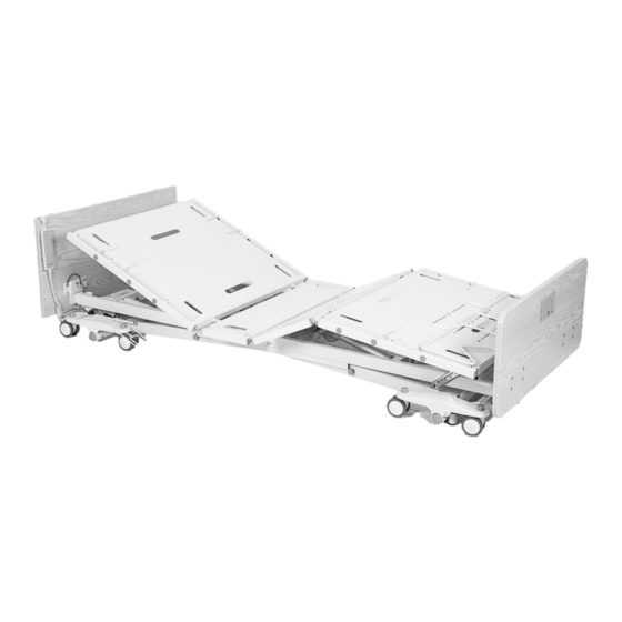
- Page 1 B337 Long-Term Care Low Profile Bed User Manual DEALERS: This manual MUST be given to the user of the bed. USER: Before using this bed, read this manual and save for future reference.
-
Page 2: Table Of Contents
Table of Contents GENERAL INFORMATION ........................2 ...................... 2 TANDARD YMBOLS AND ARNING ABELS .............................. 3 NTENDED ............................ 3 AFETY RECAUTIONS TECHNICAL SPECIFICATION .........................6 EQUIPMENT ASSEMBLY ........................7 ............................. 7 NPACKING THE ............................ 8 SSEMBLING THE EQUIPMENT OPERATION ......................... 13 ..........................13 OSITIONING THE 80”... -
Page 3: General Information
1.0 GENERAL INFORMATION 1.1 Standard Symbols and Warning Labels Warnings Signal words with symbols are used in this manual to highlight hazards or unsafe practices which could result in personal injury or property damage. See the information below for definitions of the signal words and symbols. DANGER Danger indicates an imminently hazardous situation which, if not avoided, will result in death or serious injury. -
Page 4: Intended Use
1.2 Intended Use The Costcare Long-Term Care Low Profile Beds are intended for use in within an institutional healthcare environment, i.e. nursing homes, rehabilitation care, assisted living. The bed is NOT a transport device. The wheels on the bed are for positioning the bed only. - Page 5 The mattress platform shall be kept in a flat position if the patient’s condition could lead to patient entrapment. ALWAYS keep the bed at the lowest position when the patient is unattended. 1.3.3 Performing Maintenance WARNING ONLY qualified personnel should carry out the bed maintenance. DO NOT attempt to open the pre-sealed actuator or obtain local service, for it will VOID the warranty and might result in damage.
- Page 6 1.3.5 Disposal WARNING This product has been supplied from an environmentally aware manufacturer. Where backup battery is used, DO NOT dispose of batteries in normal household waste. They MUST be taken to a proper disposal site. Contact your local waste management company for information.
-
Page 7: Technical Specification
2.0 TECHNICAL SPECIFICATION B337 Bed Height 7” – 30” Back Rest Angle 0° - 65° Knee Break Angle 0° - 35° Additional Manual Leg Lift Yes, various positions Trendelenburg / Reverse Trendelenburg ± 12° Safe Working Load (SWL) 600 lbs Max. -
Page 8: Equipment Assembly
3.0 EQUIPMENT ASSEMBLY 3.1 Unpacking the Bed WARNING To avoid injury, DO NOT attempt to remove the bed from the carton without assistance. Unpack the components from the shipping cartons. II. Upon unpacking your bed, the package should contain all of the following components. -
Page 9: Assembling The Bed
3.2 Assembling the Bed 3.2.1 Assembling the head/foot board brackets to the bed 1. With the bed raised to its highest position, step on the locking levers to lock the casters on at the foot end of the bed. 2. Turn and loosen the two black turn knobs on the underside of the bed assembly insertion slots on the head side of the bed. - Page 10 3.2.3 Assembling the footboard with staff control 1. Ensure the power is turned off before installing the footboard with staff control. 2. Following the headboard installation procedure for foot board installation. 3. An extension port is provided on the side of the bed frame. Hinge open the cap on the extension port.
- Page 11 3.2.4 Installing the mattress retaining system 1. Locate the mounting holes for the mattress retainers in the bed deck. Align and insert the mattress retaining wires through the pre-cast holes. 2. Repeat the procedure for all four side mattress retainers. 3.
- Page 12 3.2.6 Installing the rails or assist bars 1. Before installing the rails or bars, the bed should be in a flat position. 2. Unclip the metal snap ring and remove the metal pins from the mounting brackets. Holes for Swing Rail Holes for Assist Bar 3.
- Page 13 3.2.7 Control box connections Upon opening the control box, each motor connection port is color coded for ease of identification. DC. Battery Backup Port Backrest Motor Knee-break Motor Hi-Lo Motor (Front) Hi-Lo Motor (Rear) Underbed Lighting Spare Staff Control Hand Pendant 3.2.8 Installing battery backup 1.
-
Page 14: Equipment Operation
4.0 EQUIPMENT OPERATION 4.1 Positioning the Bed 1. To lock the bed, step on the red lever at the rear of the bed. 2. The caster guides on both sides of the head end casters should be lowered to prevent sideway movements. The fork opening of the caster guide should sit on top of the caster locking tab, limiting any swivel action. -
Page 15: Extend The Length Of The Bed From 80" To 84" Or 88
4.2 Extend the Length of the Bed from 80” to 84” or 88” 1. Loosen the two black knobs located on the underside of the bed frame securing the footboard frame. (Refer to Section 3) 2. Pull the footboard frame away from the bed squarely with both hands to the required length. -
Page 16: Adjusting The Extended Heel Lift
5. To extend the headboard, lift up and flip the extension piece on the back of headboard. Reinsert the steel plates into the mounting brackets on the main headboard. 4.4 Adjusting the Extended Heel Lift 1. Grip the end section of the bed platform. Lift up slowly to the preferred height. Ensure there is an audible click indicating that the deck is locked in place within the Ratcheting Bracket. -
Page 17: Using The Controller
4.5 Using the Controller The UP arrow ( ) indicates raising the corresponding parts of the bed. The DOWN arrow ( ) indicates lowering the corresponding parts of the bed. 1. Use button □ and □ to adjust the backrest up or down. 2. -
Page 18: Using The Staff Control
4.6 Using the Staff Control The UP arrow ( ) indicates raising the corresponding parts of the bed. The DOWN arrow ( ) indicates lowering the corresponding parts of the bed. The staff control can lockout functions on the hand pendant. To engage the lockout, hold down the “Lock”... -
Page 19: Operating The Bed Rails
4.8 Operating the bed rails Metal Swing Rail Raise Bed Rail: Pull the bed rail upwards until the rail is securely locked in place. Lower Bed Rail: Squeeze the release lever at the bottom corner of the bed rail and slowly lower the bed rail to its lowest position. -
Page 20: Troubleshooting Guide
5.0 TROUBLESHOOTING GUIDE SYMPTOMS POSSIBLE FAULTS POSSIBLE SOLUTIONS Bed idle when hand pendant Adjustment may be at the Check if other buttons are buttons are pressed. maximum or minimum working. position Power cord not connected or Ensure the power cord is damaged properly connected to the electrical socket and the bed. -
Page 21: Limited Warranty
In the event of a defect covered by this warranty, Costcare will, at Costcare's option, repair or replace the device. The warranty provides only for replacement of defective parts and does not cover shipping and labor charges. -
Page 22: Appendix - Service Record
APPENDIX – SERVICE RECORD DATE PERFORMED BY CONDITION REPORT... - Page 23 DATE PERFORMED BY CONDITION REPORT...
- Page 24 www.costcaremed.com 1-714-485-2206 Date of Issue: 02/01/2021...
Need help?
Do you have a question about the B337 and is the answer not in the manual?
Questions and answers