
Related Manuals for Costcare B437


Summary of Contents for Costcare B437
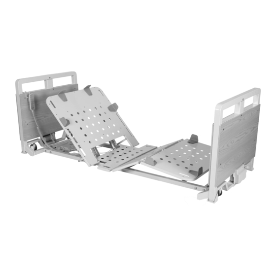
- Page 1 B437 Ultra Low Long-Term Care Bed User Manual DEALERS: This manual MUST be given to the user of the bed. USER: Before using this bed, read this manual and save for future reference.
-
Page 2: Table Of Contents
Table of Contents GENERAL INFORMATION ........................2 ...................... 2 TANDARD YMBOLS AND ARNING ABELS .............................. 3 NTENDED ............................ 3 AFETY RECAUTIONS TECHNICAL SPECIFICATION .........................6 ASSEMBLY INSTRUCTIONS........................7 UNPACKING THE BED ..........................7 ASSEMBLING THE BED ..........................8 ASSEMBLING THE BED DECK ........................8 ASSEMBLING THE HEAD/FOOT BOARD ONTO THE BED ................ -
Page 3: General Information
1.0 GENERAL INFORMATION 1.1 Standard Symbols and Warning Labels Warnings Signal words with symbols are used in this manual to highlight hazards or unsafe practices which could result in personal injury or property damage. See the information below for definitions of the signal words and symbols. DANGER Danger indicates an imminently hazardous situation which, if not avoided, will result in death or serious injury. -
Page 4: Intended Use
1.2 Intended Use The Costcare Long-Term Care Low Profile Beds are intended for use in within an institutional healthcare environment, i.e. nursing homes, rehabilitation care, assisted living. The bed is NOT a transport device. The wheels on the bed are for positioning the bed only. - Page 5 The mattress platform shall be kept in a flat position if the patient’s condition could lead to patient entrapment. ALWAYS keep the bed at the lowest position when the patient is unattended. 1.3.3 Performing Maintenance WARNING ONLY qualified personnel should carry out the bed maintenance. DO NOT attempt to open the pre-sealed actuator or obtain local service, for it will VOID the warranty and might result in damage.
- Page 6 1.3.5 Disposal WARNING This product has been supplied from an environmentally aware manufacturer. Where backup battery is used, DO NOT dispose of batteries in normal household waste. They MUST be taken to a proper disposal site. Contact your local waste management company for information.
-
Page 7: Technical Specification
2.0 TECHNICAL SPECIFICATION B437 Bed Height 2.6” – 25.6” Back Rest Angle 0° - 70° Knee Break Angle 0° - 27° Additional Manual Leg Lift Yes, various positions Trendelenburg / Reverse Trendelenburg Safe Working Load (SWL) 400 lbs Max. Patient Weight... -
Page 8: Assembly Instructions
3.0 ASSEMBLY INSTRUCTIONS 3.1 UNPACKING THE BED Unpack the components from the shipping cartons. II. Remove any zip ties holding the components to the Bed Assembly. III. Upon unpacking your bed, the package should contain all the following components. IV. Inspect the bed components for damages. If the bed is damaged, do not use the bed and contact the manufacturer. -
Page 9: Assembling The Bed
3.2 ASSEMBLING THE BED The bed comes in with the sections (head board, foot board, upper bed deck and lower bed deck) stacked, carefully lay each section on the floor. 3.3 ASSEMBLING THE BED DECK 1. With the bed decks positioned flat on the floor, join the upper and lower bed decks together. -
Page 10: Assembling The Head/Foot Board Onto The Bed
3.4 ASSEMBLING THE HEAD/FOOT BOARD ONTO THE BED 1. Lift up the upper bed deck slightly and insert the head board into the main bed frame. 2. Secure the head board to the deck with two socket screws on each side. 3. -
Page 11: Installing The Hand Pendant Clip
3.6 INSTALLING THE HAND PENDANT CLIP Clip the hand pendant clip over the two timber panels of the head board and push it down firmly. 3.7 CONNECTING CABLES TO THE CONTROL BOX Motor cables will need to be connected to the control box, located at the center of the bed. - Page 12 Backup Battery Backrest Motor 1 Backrest Motor 2 Headboard Motor (if applicable) Hand Control Footboard Motor Kneebreak Motor Underbed lighting Nursing Control (if applicable) (if applicable) 3. Connect all cables and reinstate the locking lid, ensure there is an audible click.
-
Page 13: Installing Battery Backup (Optional )
3.8 INSTALLING BATTERY BACKUP (Optional) 1. Switch the power supply off when installing the backup battery. 2. Affix the backup battery with nuts and bolts to the left of the control box, on the same holding plate. 3. Open the control box locking lid by pressing in the sides and lift it up, to expose the connections ports. -
Page 14: Installing The Rails (Optional)
3.9 INSTALLING THE RAILS (Optional) 1. Before installing the rails, the bed should be in the flat position. 2. Unclip the metal snap ring and remove the metal pins from the rail mounting brackets. 3. Hook the rail bracket onto the edge of the bed decking. Align the rail bracket mounting holes with the bed deck mounting holes. - Page 15 Holes for Assist Bars Holes for Swing Rails...
-
Page 16: Equipment Operation
4.0 EQUIPMENT OPERATION 4.1 POSITIONING THE BED To position the bed, use the castors to move the bed. Once the bed is in its desired location, lock all castors in place. 4.2 USING THE CONTROLLER The UP arrow ( ) indicates raising the corresponding parts of the bed. The DOWN arrow ( ) indicates lowering the corresponding parts of the bed. -
Page 17: Resetting The Bed
4.3 Resetting the Bed Where a connection fault is identified and rectified, the control system will require a reset in order to operate again. 1. Pressed and hold the control button for lowering the backrest and kneebreak. Continue to hold down the button for 10 seconds after the mattress platform is completely flat. -
Page 18: Folding And Transporting The Bed
4.5 FOLDING AND TRANSPORTING THE BED The bed can be disassembled and transferred in a compact manner using the transport bars. 1. Reverse the bed installation procedure to disassemble the bed into four sections, the head board, the foot board, the upper and lower bed decks. 2. -
Page 19: Troubleshooting Guide
5.0 TROUBLESHOOTING GUIDE SYMPTOMS FAULTS SOLUTIONS Bed idle when hand pendant Adjustment may be at the Check if other buttons are buttons are pressed. maximum or minimum working. position. Power cable not connected Ensure the power cable is or damaged. properly connected to the electrical socket and the bed. -
Page 20: Limited Warranty
In the event of a defect covered by this warranty, Costcare will, at Costcare's option, repair or replace the device. The warranty provides only for replacement of defective parts and does not cover shipping and labor charges. -
Page 21: Service Record
SERVICE RECORD DATE PERFORMED BY CONDITION REPORT... - Page 22 DATE PERFORMED BY CONDITION REPORT...
- Page 23 www.costcaremed.com 1-714-485-2206 Date of Issue: 29/03/2021...
Need help?
Do you have a question about the B437 and is the answer not in the manual?
Questions and answers