Table of Contents
Advertisement
Quick Links
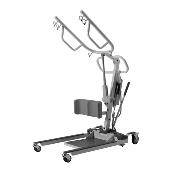
Electric Stand Assist (Item: L440C)
Mobile Patient Lift
User Manual
DEALERS: This manual MUST be given to the user of the patient lift.
USER: Before using this patient lift, read this manual and save for future reference.
CAUTION: DO NOT attempt to adjust or operate patient lift without carefully reading all instruction in
this manual.
Advertisement
Table of Contents

Related Manuals for Costcare L440C


Summary of Contents for Costcare L440C
- Page 1 Electric Stand Assist (Item: L440C) Mobile Patient Lift User Manual DEALERS: This manual MUST be given to the user of the patient lift. USER: Before using this patient lift, read this manual and save for future reference. CAUTION: DO NOT attempt to adjust or operate patient lift without carefully reading all instruction in...
-
Page 2: Table Of Contents
Table of Contents GENERAL INFORMATION ........................2 ...................... 2 TANDARD YMBOLS AND ARNING ABELS .............................. 2 NTENDED ............................ 3 AFETY RECAUTIONS ............................7 XPECTANCY TECHNICAL SPECIFICATION .........................8 ..............................8 ATIENT EQUIPMENT ASSEMBLY ........................9 ......................... 9 NPACKING THE ATIENT ........................11 SSEMBLING THE PATIENT LIFT EQUIPMENT OPERATION ......................... -
Page 3: General Information
1.0 GENERAL INFORMATION 1.1 Standard Symbols and Warning Labels Warnings Signal words with symbols are used in this manual to highlight hazards or unsafe practices which could result in personal injury or property damage. See the information below for definitions of the signal words and symbols. DANGER Danger indicates an imminently hazardous situation which, if not avoided, will result in death or serious injury. -
Page 4: Safety Precautions
The lifters are intended for users who fully understood the content of this manual and is not intended for use by children. 1.3 Safety Precautions 1.3.1 Assembling the Lift WARNING DO NOT overtighten the mounting hardware as this will damage the mounting brackets. - Page 5 After each wash (in accordance with instructions on the sling), inspect sling(s) for wear, tears, and loose stitching. Bleached, torn, cut, frayed, or broken slings are unsafe and could result in injury, and should be DISCARDED immediately. DO NOT alter slings. Be sure to check the sling attachments each time the sling is removed and replaced, to ensure that it is properly attached before the patient is removed from a stationary object (bed, chair or commode).
- Page 6 During transfer, with patient in a sling attached to the lift, DO NOT roll caster base over uneven surfaces that could cause the patient lift to tip over. Use steering handle on the mast at all times to maneuver the patient lift. 1.3.5 Transferring the Patient WARNING When the patient is elevated a few inches off a stationary surface and before moving...
- Page 7 1.3.7 Electrical and Grounding WARNING Thoroughly read through the battery/battery charger information prior to installing, servicing or operating your patient lift. GROUNDING DO NOT, under any circumstances, cut or remove the grounding prong from any plug. Some devices are equipped with three-prong (grounding) plugs for protection against possible shock hazards.
-
Page 8: Life Expectancy
1.4 Life Expectancy The lift expectancy of the lift is eight years, presuming that the product is used daily and in accordance with safety instructions and maintenance instructions stated in this manual. -
Page 9: Technical Specification
2.0 TECHNICAL SPECIFICATION 2.1 Patient Lift L440C Electric Stand Assist Lift 70” Height at Sling Hook-up - MAX Height at Sling Hook-up - MIN 33.6” Base Width OPEN 40” BASE Width Closed 25” Base Height (Clearance) 4.5” Base Length 48”... -
Page 10: Equipment Assembly
3.0 EQUIPMENT ASSEMBLY 3.1 Unpacking the Patient Lift WARNING To avoid injury, DO NOT attempt to remove the lift from the carton without assistance. Unpack the components from the shipping carton. II. Upon unpacking your patient lift, the package should contain all of the following components. - Page 11 Tools also provided in the package: Allen Wrench x 2 (size M8 & M10) Wrench YOU SHOULD PREPARE THE FOLLOWING TOOLS FOR THE LIFT ASSEMBLY: Crosshead Screwdriver x 1 Not all items provided in the carton are shown in the above. Pinch guards, bolts, washers and nuts are fastened to their intended locations and therefore omitted from the illustration.
-
Page 12: Assembling The Patient Lift
3.2 Assembling the patient lift WARNING Use only parts supplied by the manufacturer for assembly. The base legs, the mast, boom, and actuator assembly are manufactured to specifications that assure correct alignment of all parts for safe operation. 3.2.1 Assembling the mast to the base Step on the locking levers to lock the two rear casters at the base. - Page 13 WARNING For storage or transport, the mast may be disconnected from the base. Each time the mast is removed and returned to the base, the mast MUST be properly secured to the base assembly. 3.2.2 Assembling the boom to the mast The bottom of the actuator assembly will be preassembled to the mast mounting bracket.
- Page 14 Be sure that the bolt is completely through the holes of the boom assembly mounting bracket and the actuator assembly. The boom assembly will pivot easily if the mounting hardware is aligned properly when the boom assembly is secured. 3.2.4 Assembling the control box to the mast Slide the control box onto the mounting bracket on the boom.
- Page 15 3.2.5 Installing the shifter handle Line-up the shifter handle opening with the threaded connector at the base. II. Turn the shifter handle clockwise and securely tighten into the base. III. Secure the shifting handle in place with a cross head screw.
-
Page 16: Equipment Operation
4.0 EQUIPMENT OPERATION 4.1 Operating the patient lift 4.1.1 Closing/Opening the Legs of the lift base Stand at the rear of the lifter and grasp the shifter handle. Swivel the shifter handle to open and close the legs of the base. The shifter handle MUST lock into its mounting slot to lock the legs in the full close/open position. - Page 17 4.1.3 Raising/lowering the electric lift WARNING The rear casters of the patient lift should not be locked when lifting an individual. Locked casters could cause the lift to tip and endanger the patient and assistants. It is recommended that the rear casters be left unlocked during lifting procedures to allow the patient lift to stabilize itself when the patient is initially lifted from a chair, bed or any stationary object.
- Page 18 Where the hand pendant is absent or at fault, the control box can be used to lower and raise the patient lift. The buttons for raising and lowering the lift is located on the front of the control box above the emergency stop button.
-
Page 19: Charging The Battery
4.2 Charging the Battery It is recommended that the battery should be recharged daily to prolong battery life. The battery status can be viewed on the LCD display at the front of the control box. 4.2.1 Charging the battery with power cord Use the charging cord provided in the carton, plug the pins into an appropriate grounded electrical socket. - Page 20 4.2.2 Charging the battery with standalone charger The standalone charger is an accessory and should be ordered separately. Flip open the hinged lid at the top of the control box to expose the internal battery. II. Lift the battery up and out away from the control box. III.
-
Page 21: Lifting The Patient
5.0 LIFTING THE PATIENT 5.1 Preparing the lift for use 5.1.1 Positioning the lift for use With the legs of the base open and locked, use the steering handle to push the patient lift into position. II. Lower the patient lift for easy attachment of the sling. WARNING The legs of the lift must be in the maximum open position and the shifter handle locked in place for optimum stability and safety. -
Page 22: Lifting/Moving The Patient
5.1.3 Prepare the Sling at Seated Position WARNING Where the patient is seated in a wheelchair, the wheels MUST be locked when putting on the sling. Lean patient forward and set the folded sling behind the patient’s back. Set the sling as far down as possible until it touches the back of the seat. -
Page 23: Transferring The Patient
WARNING When the patient is elevated a few inches off the surface of the bed, check again to make sure that all hardware or straps are properly connected. If any attachment is NOT properly in place, lower the patient back onto the bed and rectify the issue. 5.3 Transferring the patient WARNING When the patient is elevated a few inches off a stationary surface and before moving... - Page 24 VI. To return patient to bed, reverse procedures concerning lifting the patient, operation and sling attachment. VII. To return or place patient in a wheel chair, refer to Transferring the patient to a wheelchair section of this manual. The lift is NOT a transport device. Where it is difficult to maneuver the lift towards the commode or the bathroom facility is too far from the bed, the patient MUST be transported to a wheel chair first.
-
Page 25: Maintenance & Cleaning
6.0 MAINTENANCE & CLEANING 6.1 Maintenance Schedule INSTITUTIONAL IN-HOME INSPECT & INSPECT & ITEM INITIALLY ADJUST ADJUST (MONTHLY) (6 MONTHS) THE CASTER BASE - Base opens/closes with ease - Inspect for missing hardware - Inspect casters and axle bolts for tightness - Inspect casters for smooth swivel and roll - Inspect and clear debris on casters - Inspect the patient stand for wear and... -
Page 26: Detecting Wear And Damage
INSTITUTIONAL IN-HOME INSPECT & INSPECT & ITEM INITIALLY ADJUST ADJUST (MONTHLY) (6 MONTHS) THE ELECTRIC ACTUATOR ASSEMBLY - Inspect hardware on mast and boom - Inspect joints with mast and boom - Inspect for wear and tear. Return to the supplier where damaged - Cycle to ensure smooth quiet operation SLING AND HARDWARE... -
Page 27: Checking And Tightening Mast Pivot Bolt
The casters MUST swivel and roll smoothly. A light grease (waterproof auto lubricant) may be applied to the ball bearing swivel of the casters once a year. Apply more frequently if the casters are exposed to extreme moist conditions. Refer to the below figure for lubrication points. Lubricate all pivot points. Wipe all excess lubricant from lift surface. -
Page 28: Replacing The Electric Actuator
6.5 Replacing the Electric Actuator Remove the shoulder bolt, nut, and washer that secure the electric actuator to the mast mounting bracket. II. Rest the boom on your shoulder and remove the bolt, nut, washer, and plastic bushing from the boom mounting bracket. III. -
Page 29: Replacing The Knee Pad
6.6 Replacing the Knee Pad The knee pad comes attached to its supporting bracket on the mast, with locking screws. II. Remove the 4 No. locking screws at the rear of the knee pad. III. Replace the knee pad and tighten to the mounting bracket with locking screws. 6.7 Replacing the Patient Stand Remove the lock nuts on either side of the foot stand that secures the stand to the lift base. -
Page 30: Maintaining The Base Adjustment
6.8 Maintaining the Base Adjustment The base adjustment should not require any attention other than: Check the squareness of the legs when in the closed position. II. Place a square on the inside of the legs and base to determine the 90° alignment. III. - Page 31 6.9.2 Replacing front casters Turn and place the lift on its side. II. Remove the bolt and nut securing the existing front caster assembly to the fork. III. Position the new/existing washer between the two new casters. IV. Align the mounting holes in the new front caster assembly and the fork. V.
-
Page 32: Cleaning
6.9.3 Replacing caster forks Turn and place the lift on its side. II. Remove the front or rear caster from the lift. Refer to Section 6.9.1 and 6.9.2. III. Unscrew the existing fork from the base. IV. Install the new fork onto the base. V. -
Page 33: Troubleshooting Guide
7.0 TROUBLESHOOTING GUIDE SYMPTOMS FAULTS SOLUTIONS Actuator idle when lift Battery Low. Recharge battery with power buttons are pressed. cable or wall charger. Hand control or actuator Ensure tight connection of all connector loose. connectors to control box. RED emergency stop button Rotate the emergency button pressed in. -
Page 34: Limited Warranty
In the event of a defect covered by this warranty, Costcare will, at Costcare's option, repair or replace the device. The warranty provides only for replacement of defective parts and does not cover shipping and labor charges. -
Page 35: Appendix - Service Record
APPENDIX – SERVICE RECORD DATE PERFORMED BY CONDITION REPORT... - Page 36 www.costcaremed.com 1-714-349-8331...
Need help?
Do you have a question about the L440C and is the answer not in the manual?
Questions and answers