
Related Manuals for Costcare L350C


Summary of Contents for Costcare L350C
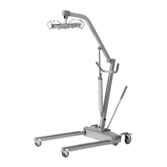
- Page 1 Manual Hydraulic (Item: L350C) Mobile Patient Lift User Manual DEALERS: This manual MUST be given to the user of the patient lift. USER: Before using this patient lift, read this manual and save for future reference.
-
Page 2: Table Of Contents
Table of Contents GENERAL INFORMATION ........................2 ...................... 2 TANDARD YMBOLS AND ARNING ABELS .............................. 2 NTENDED ............................ 3 AFETY RECAUTIONS ............................6 XPECTANCY TECHNICAL SPECIFICATION .........................7 ..............................7 ATIENT EQUIPMENT ASSEMBLY ........................8 ......................... 8 NPACKING THE ATIENT ........................10 SSEMBLING THE PATIENT LIFT EQUIPMENT OPERATION ......................... -
Page 3: General Information
1.0 GENERAL INFORMATION 1.1 Standard Symbols and Warning Labels Warnings Signal words with symbols are used in this manual to highlight hazards or unsafe practices which could result in personal injury or property damage. See the information below for definitions of the signal words and symbols. DANGER Danger indicates an imminently hazardous situation which, if not avoided, will result in death or serious injury. -
Page 4: Safety Precautions
The lifts are intended for users who fully understood the content of this manual and is not intended for use by children. 1.3 Safety Precautions 1.3.1 Assembling the Lift WARNING DO NOT overtighten the mounting hardware as this will damage the mounting brackets. - Page 5 DO NOT alter slings. Be sure to check the sling attachments each time the sling is removed and replaced, to ensure that it is properly attached before the patient is removed from a stationary object (bed, chair or commode). If the patient is in a wheelchair, secure the wheel locks in place to prevent chair movements that could lead to potential falls.
- Page 6 1.3.5 Transferring the Patient WARNING When the patient is elevated a few inches off a stationary surface and before moving the patient, check again to make sure that all hardware or straps are properly connected. If any attachment is NOT properly in place, lower the patient back onto the bed and rectify the issue.
-
Page 7: Life Expectancy
Regular maintenance of patient lifts and accessories is necessary to ensure proper operation. DO NOT overtighten mounting hardware. This will damage mounting brackets. 1.3.7 Disposal WARNING This product has been supplied from an environmentally aware manufacturer. This product may contain substances that could be harmful to the environment if disposed of in places (landfills) that are not appropriate according to legislation. -
Page 8: Technical Specification
2.0 TECHNICAL SPECIFICATION 2.1 Patient Lift L350C Model Type Hydraulic Manual Lift Height at Sling Hook-up - MAX 67” Height at Sling Hook-up - MIN 20.8” Base Width OPEN 40” BASE Width Closed 25” Base Height (Clearance) 4.5” Base Length 48”... -
Page 9: Equipment Assembly
3.0 EQUIPMENT ASSEMBLY 3.1 Unpacking the Patient Lift WARNING To avoid injury, DO NOT attempt to remove the lift from the carton without assistance. Unpack the components from the shipping carton. II. Upon unpacking your patient lift, the package should contain all of the following components. - Page 10 Shifter Handle x 1 YOU SHOULD PREPARE THE FOLLOWING TOOLS FOR THE LIFT ASSEMBLY: Crosshead Screwdriver x 1 (For Bariatric Lift Only) Not all items provided in the carton are shown in the above. Pinch guards, bolts, washers and nuts are fastened to their intended locations and therefore omitted from the illustration.
-
Page 11: Assembling The Patient Lift
3.2 Assembling the patient lift WARNING Use only parts supplied by the manufacturer for assembly. The base legs, the mast, boom, hydraulic pump assembly and the swivel bar are manufactured to specifications that assure correct alignment of all parts for safe operation. 3.2.1 Assembling the mast to the base Step on the locking levers to lock the two rear casters at the base. - Page 12 WARNING For storage or transport, the mast may be disconnected from the base. Each time the mast is removed and returned to the base, the mast MUST be properly secured to the base assembly. 3.2.2 Assembling the boom to the mast Step on the locking levers to lock the two rear casters at the base.
- Page 13 3.2.3 Assembling the hydraulic pump to the boom The bottom of the hydraulic pump assembly will be preassembled to the mast mounting bracket. Remove the shoulder bolt, washer and nut fastened to the boom mounting bracket. II. Lift-up on the boom and place it on your left shoulder. III.
- Page 14 3.2.4 Installing the shifter handle Line-up the shifter handle opening with the threaded connector at the base. II. Turn the shifter handle clockwise and securely tighten into the base. III. Secure the shifting handle in place with a cross head screw.
-
Page 15: Equipment Operation
4.0 EQUIPMENT OPERATION 4.1 Operating the patient lift 4.1.1 Closing/Opening the Legs of the lift base Stand at the rear of the lifter and grasp the shifter handle. Swivel the shifter handle to open and close the legs of the base. The shifter handle MUST lock into its mounting slot to lock the legs in the full close/open position. - Page 16 4.1.2 Raising/lowering the lift WARNING The rear casters of the patient lift should not be locked when lifting an individual. Locked casters could cause the lift to tip and endanger the patient and assistants. It is recommended that the rear casters be left unlocked during lifting procedures to allow the patient lift to stabilize itself when the patient is initially lifted from a chair, bed or any stationary object.
-
Page 17: Lifting The Patient
5.0 LIFTING THE PATIENT 5.1 Preparing the lift for use 5.1.1 Positioning the lift for use With the legs of the base open and locked, use the steering handle to push the patient lift into position. II. Lower the patient lift for easy attachment of the sling. WARNING The legs of the lift must be in the maximum open position and the shifter handle locked in place for optimum stability and safety. -
Page 18: Lifting/Moving The Patient
5.1.3 Prepare the Sling at Seated Position WARNING Where the patient is seated in a wheelchair, the wheels MUST be locked when putting on the sling. Lean patient forward and set the folded sling behind the patient’s back. Set the sling as far down as possible until it touches the back of the seat. -
Page 19: Transferring The Patient
connected. If any attachment is NOT properly in place, lower the patient back onto the bed and rectify the issue. III. When the patient is lifted from the bed (with the patient’s head supported), he/she will be raised to a sitting position. IV. - Page 20 V. Lift up on legs with one hand and tilt the patient back with the other hand. VI. The second assistant should pull the patient lift away from the car until the patient is completely clear of the door frame. VII.
- Page 21 5.3.3 Transferring the patient for using a bath Move the patient from the bed onto the wheelchair, refer to Transferring the patient to a wheelchair section of this manual. II. The patient should be elevated high enough to clear the wheelchair and their weight supported by the lift.
-
Page 22: Maintenance & Cleaning
6.0 MAINTENANCE & CLEANING 6.1 Maintenance Schedule INSTITUTIONAL IN-HOME INSPECT & INSPECT & ITEM INITIALLY ADJUST ADJUST (MONTHLY) (6 MONTHS) THE CASTER BASE - Base opens/closes with ease - Inspect for missing hardware - Inspect casters and axle bolts for tightness - Inspect casters for smooth swivel and roll - Inspect and clear debris on casters SHIFTER HANDLE... -
Page 23: Detecting Wear And Damage
INSTITUTIONAL IN-HOME INSPECT & INSPECT & ITEM INITIALLY ADJUST ADJUST (MONTHLY) (6 MONTHS) THE HYDRAULIC PUMP ASSEMBLY - Inspect hardware on mast and boom - Inspect joints with mast and boom - Inspect for wear and deformation - Check for leakage SLING AND HARDWARE - Check all sling attachments EACH TIME IT IS USED* to ensure proper connection and... -
Page 24: Checking And Tightening Mast Pivot Bolt
The casters MUST swivel and roll smoothly. A light grease (waterproof auto lubricant) may be applied to the ball bearing swivel of the casters once a year. Apply more frequently if the casters are exposed to extreme moist conditions. Refer to the below figure for lubrication points. Lubricate all pivot points. Wipe all excess lubricant from lift surface. -
Page 25: Replacing The Hydraulic Pump
6.5 Replacing the Hydraulic Pump Remove the shoulder bolt, nut, and washer that secure the hydraulic pump to the mast mounting bracket. II. Rest the boom on your shoulder, rotate lock nut at the bottom of the hydraulic pump anti-clockwise to loosen the hydraulic pump from the mast mounting bracket. -
Page 26: Replacing The Swivel Bar
6.6 Replacing the Swivel Bar The hanger bar comes attached to the boom with bolt, nut, washers, and pinch guard. II. Remove existing hardware and replace the hanger bar. WARNING After the first year of use, the hooks of the swivel bar and mounting brackets of the boom should be inspected every six months to determine the extent of wear. -
Page 27: Maintaining The Base Adjustment
6.7 Maintaining the Base Adjustment The base adjustment should not require any attention other than: Check the squareness of the legs when in the closed position. II. Place a square on the inside of the legs and base to determine the 90° alignment. III. - Page 28 6.8.2 Replacing front casters Turn and place the lift on its side. II. Remove the bolt and nut securing the existing front caster assembly to the fork. III. Position the new/existing washer between the two new casters. IV. Align the mounting holes in the new front caster assembly and the fork. V.
-
Page 29: Cleaning
6.8.3 Replacing caster forks Turn and place the lift on its side. II. Remove the front or rear caster from the lift. Refer to Section 6.8.1 and 6.8.2. III. Unscrew the existing fork from the base. IV. Install the new fork onto the base. V. -
Page 30: Troubleshooting Guide
7.0 TROUBLESHOOTING GUIDE SYMPTOMS FAULTS SOLUTIONS Pump assembly idle when Hydraulic pump in need of Reduce load. Replace if worn. pump handle is engaged. service or load is too high. Patient lift feels loose. Mast/Base joint loose. Refer to Section 3.2 & 6.4. Casters/Brakes noisy or stiff. -
Page 31: Limited Warranty
In the event of a defect covered by this warranty, Costcare will, at Costcare's option, repair or replace the device. The warranty provides only for replacement of defective parts and does not cover shipping and labor charges. -
Page 32: Appendix - Service Record
APPENDIX – SERVICE RECORD DATE PERFORMED BY CONDITION REPORT... - Page 33 DATE PERFORMED BY CONDITION REPORT...
- Page 34 www.costcaremed.com 1-714-349-8331...
Need help?
Do you have a question about the L350C and is the answer not in the manual?
Questions and answers