Advertisement
Table of Contents
- 1 About this Manual
- 2 Pump Identification
- 3 Declaration of Conformity
- 4 Identification Code
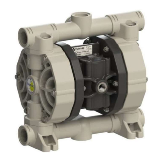
- 5 Pump Description
- 6 Technical Features
- 7 Warranty
- 8 Safety Rules
- 9 Installation and Use Instructions
- 10 Transport and Positioning
- 11 Installation
- 12 Product Circuit Maintenance
- 13 Troubleshooting
- 14 Demolition and Disposal
- Download this manual
Advertisement
Table of Contents


Need help?
Do you have a question about the PHOENIX and is the answer not in the manual?
Questions and answers