
Related Manuals for LG GR-L28AK Series


Summary of Contents for LG GR-L28AK Series
- Page 1 REFRIGERATOR SERVICE MANUAL CAUTION BEFORE SERVICING THE UNIT, READ THE "SAFETY PRECAUTIONS" IN THIS MANUAL. MODEL : GR-L28AK**...
-
Page 2: Table Of Contents
CONTENTS SAFETY PRECAUTIONS ...............................2 1. SPECIFICATIONS ................................3 2. PARTS IDENTIFICATION ..............................4 3. DISASSEMBLY ................................5-16 REMOVING AND REPLACING REFRIGERATOR DOORS .....................5 DOOR ....................................6-7 DOOR ALIGNMENT ............................7 FAN AND FAN MOTOR(EVAPORATOR) .......................7 DEFROST CONTROL ASSEMBLY .............................8 LAMP ................................8 MULTI DUCT ..............................9 MAIN PWB ..................................9 DISPENSER ..................................9 DISPLAY PCB REPLACEMENT ............................9 ICE BUTTON ASSEMBLY ..............................9... -
Page 3: Specifications
1. SPECIFICATIONS 28 cu. ft. / 025 cu. ft ITEMS SPECIFICATIONS ITEMS SPECIFICATIONS DOOR DESIGN Side Rounded VEGETABLE TRAY Clear Drawer Type 3 /4 3 /8 3 /4 DIMENSIONS (inches) X 35 X 69 (WXDXH) 28cu.ft COMPRESSOR Recipro NET WEIGHT (pounds) 359lb. -
Page 4: Parts Identification
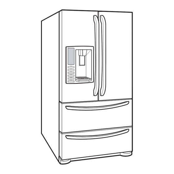
2. PARTS IDENTIFICATION ADJUSTABLE REFRIGERATOR SHELVING The refrigerator compartment shelves are adjustable to allow flexibility for storage needs. GALLON STORAGE BINS Three interchangeable bins can be arranged to suit your storage needs. REMOVABLE ICE STORAGE BIN The ice storage bin can be removed to fill ice buckets,coolers,or pitchers. -
Page 5: Disassembly
3. DISASSEMBLY 3-1 REMOVING AND REPLACING REFRIGERATOR DOORS Removing Refrigerator Door CAUTION: Before you begin, unplug the refrigerator. Remove food and bins from doors. Left Door -FIG. 2 1. Disconnect water supply tube by pushing back on the disconnect ring (4).-FIG. 1 2. -
Page 6: Door
3-2 DOOR Door Gasket Replacement 1. Insert gasket bracket clips Door Gasket Removal 1) Insert gasket bracket edge beneath door frame edge. 1. Remove door frame cover 2) Turn upper gasket bracket spring so that the spring Starting at top of cover and working down, snap cover ends are in the door channel. -
Page 7: Door Alignment
2) Press gasket into channels on the three remaining 3-3 DOOR ALIGNMENT sides of door. If the space between your doors is uneven, follow the instructions below to align the doors: Remove the Base Grillie. Turn the leveling legs (CCW) to raise or (CW) to lower the height of the front of the refrigerator by using flat blade screw driver or 11/32"... -
Page 8: Defrost Control Assembly
* Ice Fan Scroll Assembly Replacement 3-6 LAMP Unplug Refrigerator, or disconnect power at the circuit 1) Remove the plastic guide for slides on left side by breaker. unscrewing phillips head screws. If necessary, remove top shelf or shelves. 2) Pull out the cover sensor to disassemble using tools 3-6-1 Refrigerator Compartment Lamp shown in the figure. -
Page 9: Multi Duct
3-7 MULTI DUCT 1. Remove the upper and lower Caps by using a flat screwdriver, and remove 2 screws. (Figure 16) 3) If nozzle is interfered with button, 4) Rmove the 2. Disconnect the lead wire push and pull out the bottom of connected part on the bottom position. -
Page 10: Water Button Assembly
3-13 WATER BUTTON ASSEMBLY 3-15 ICEMAKER ASSEMBLY 1) Romove screws. 1) Loosen two screws as shown in the first picture. 2) Grasp the Button assembly and lift up. Button Lever 2) Disconnect the wire harness & ground screw replace theIcemaker assembly in the reverse order of removal. 3-14 ICE CORNER DOOR REPLACEMENT 1) Loosen the front screw as shown in the picture. -
Page 11: Cap Duct Motor Replacement
3-16 CAP DUCT MOTOR REPLACEMENT 3-17 AUGER MOTOR COVER 1) Separate the Housing of the Cap Duct Motor. 1) After removing the icemaker remove the (5) stainless screws holding the auger motor cover, shown in the picutres below. 2) Unscrew 3 screws to disassemble the motor. 2) Grip the bottom of motor cover assembly and pull out it. -
Page 12: How To Remove A Door Ice Bin
3-18 HOW TO REMOVE A ICE BIN 3-19 HOW TO INSERT A ICE BIN 1) Grip the handles, as shown in the picture. 1) Insert the Ice Bin, slightly tilting it to avoid touching the Icemaker. (especially, icemaker lever) 2) Lift the lower part slightly. Insert the ice bin carefully avoid contacting the automatic shut off arm. -
Page 13: How To Remove And Reinstall The Pullout Drawer
3-20 HOW TO REMOVE AND REINSTALL THE PULLOUT DRAWER 3-20-1 Follow Steps to Remove Step 1) Open the freezer door. Step 2) Remove the lower basket. Step 3) Remove the two screws from the guide rails Step 4) Lift the freezer door up to unhook it from the rail (one from each side). - Page 14 3-20-2 Follow Steps to Reinstall Step 1) Reinstall the right side gear into the clip. Step 2) Insert the rail into the right side gear. Gears do not Step 3) Insert the rail into the left side gear, and insert the need to be perpendicular to each other.
-
Page 15: Water Valve Disassembly Method
3-21 WATER VALVE DISASSEMBLY METHOD 3-22 FAN AND FAN MOTOR DISASSEMBLY METHOD 1) Turn off the water. Then separate the water line from the 1) Using a short screwdriver, loosen one SCREW in DRAIN valve. PIPE ASSEMBLY and one connected to the MOTOR COVER. -
Page 16: Top Drawer
3-23 TOP DRAWER To remove the freezer drawer, pull the drawer open to full extension. Remove the drawer and Ice Bin lifting the basket from the rail system. 3-24 BOTTOM DRAWER To remove the freezer drawer, pull the drawer open to full extension. Remove the lower DuraBase ®basket by lifting the basket from the rail system. -
Page 17: Adjustment
4. ADJUSTMENT 4-1 COMPRESSOR 4-2-3 PTC-Applied Circuit Diagram 4-1-1 Role Starting Method for the Motor The compressor intakes low temperature and low pressure gas from the evaporator of the refrigerator and compresses OVERLOAD PROTECTOR this gas to high-temperature and high-pressure gas. It then delivers the gas to the condenser. -
Page 18: Olp (Overload Protector)
4-3 OLP (OVERLOAD PROTECTOR) 4-4 TO REMOVE THE COVER PTC 4-3-1 Definition of OLP (1) OLP (OVERLOAD PROTECTOR) is attached to the Compressor and protects the Motor by opening the circuit to the Motor if the temperature rises and activating the bimetal spring in the OLP. (2) When high current flows to the Compressor motor, the Bimetal works by heating the heater inside the OLP, and the OLP protects the Motor by cutting off the current... -
Page 19: Circuit Diagram
5. CIRCUIT DIAGRAM - 19 -... -
Page 20: Troubleshooting
6. TROUBLESHOOTING 6-1. Error Code Summary WARNING: When you check the Resistance values, be sure to turn off the power. And wait for the voltage-discharge sufficiently. NOTE) 3 hours before the error : Press the Ice Plus button and Freezer button simultaneously 3 hours after the error : All errors, except for "Er rt"... -
Page 21: Troubleshtooting With Error
6-2. Troubleshooting With Error Freezer Sensor Error Is Er-FS displayed? Disconnect CON6 and Replace measure the value. Is F-sensor resistance value between (Position pins 11 & 12 of CON6 as No : 610C) below? (BL/WH to BL/WH) pin11 pin12 Is the connection loose? Reconnect Test Point Result... - Page 22 Refrigerator Sensor Error Is Er-rS displayed? Disconnect CON6 and Replace measure the value. Is R-sensor resistance value between (Position pins 9 & 10 of CON6 as No : 610B) below? (WH to WH) pin9 pin10 Is the connection loose? Reconnect pin9 pin10 Test Point Result...
- Page 23 Defrost Sensor Error Is Er-dS displayed? Is resistance value between Replace pins 1 & 2 of Housing- A as D-sensor below? (BO to BO) (Position No :400A) pin1 pin2 Is the connection loose? Reconnect Checking Open or Short of wire Test Point Result Pin1 To pin2...
- Page 24 Icing Room Sensor Error Is Er-IS displayed? Is resistance value between Replace the pins 1 & 2 of Housing- A as Icing-Sensor below? (BL to BL) (Position No : 600B) Is the connection loose? Reconnect Display PWB Inner of Icing door pin2 BL pin1 BL Checking Open or Short...
- Page 25 Pantry Sensor Error Replace Is resistance value between Is Er-SS displayed? Pantry- pins 3 & 6 of Housing- A as sensor below? (BN to BN) Is the connection loose? Reconnect pin3 pin6 Checking Open or Short of wire Power Off Test Point Result Tip : To protection of MICOM...
- Page 26 Defrost Heater Error Is Er-dH displayed? Enter the TEST 3 MODE Replace Is the voltage value between MAIN PWB pins 10 (BO) and 4 (BL) of (Position No CON3 115 V AC? : 500A) Is the connection loose? Reconnect Pin4 BL Pin10 BO Relay operation Test Point Result...
- Page 27 Is the resistance value Is the resistance value of Replace Normal between pins 10 (BO) And heater like as below? Heater 4 (BL) of CON3 like as below? (Position No : 408A) Pin4 BL Pin10 BO Resistance Test Point Result Heater Resistance (1) To (2) 34 ~ 42...
- Page 28 Freezer Fan Error Is Er-FF displayed? Does the cold-air come out Check fan motor of the top of the Grill Fan (Connector, under Test1 mode ? Frozen, Locked) and replace. Is the connection loose? Reconnect Is the feedback voltage Replace MAIN PWB between pin7 and pin8 of CON4 like as below?
- Page 29 Condenser Fan Error Is the condenser fan Check fan motor Is Er-CF displayed? rotate under Test1 mode? (Connector, Locked, mouse) and replace. (Position No : 420A) Is the connection loose? Reconnect Is the feedback voltage Replace MAIN PWB between pin13 and pin14 Replace Reset and of CON4 like as below?
- Page 30 Icing Room Fan Error Is Er-IF displayed? Does the cold-air come out Check fan motor of the side duct under the (Connector, Test1 Mode? Frozen,Locked) and replace. Is the connection loose? Reconnect Is the feedback voltage Replace between pin10 and pin11 Reset and Replace MAIN PWB...
- Page 31 Refrigerator Fan Error Is Er-rF displayed? Does the cold-air come out Check fan motor of the top of the main duct (Connector, under Test1 mode ? Frozen, Locked) and replace. Is the connection loose? Reconnect Is the feedback voltage between pin4 and pin5 of CON4 like as below? (from motor to main board) Reset and...
- Page 32 Communication Error Is Er-CO displayed? Display PWB Replace the Is the voltage between Display PWB pin8 and pin9 of CON101 (Position No : 0 V or 5 V? 501A) Pin5 WH/ Display PWB Reconnect Is the connection loose? Pin4 BO Transmitter Voltages Test Point Result...
- Page 33 MAIN PWB Main PWB Replace Reconnect Is the connection loose? Is the voltage between MAIN PWB pin3 and pin5 of CON5 0 V (Position No or 5 V? : 500A) Pin3 WH/ Pin5 WH/ Main PWB Replace Is the voltage between MAIN PWB Transmitter Voltages pin 3 and pin 4 of CON5 0V...
-
Page 34: Troubleshtooting Else
6-3. Troubleshooting Else CUBE Mode doesn’t work Dispenser PWB In CUBE Mode, Replace Reconnect Is the connection loose? Is the voltage between pin2 Dispenser and pin12 of CON2 like as below, while pushing the (Position No : ICE lever switch? 500C) Pin2 WH Pin12 BK... - Page 35 Replace In CUBE Mode, Replace Is the resistance value Auger Motor Is the voltage between pin2 Dispenser between (1) and (2) of the (Position No and pin6 of CON2 like as Auger motor like as below? : 606A) below, while pushing the (Position ICE lever switch? No : 500C)
- Page 36 Is the condition of Replace the micro switch like as Micro below? Switch (Position No : 402C) Status Tester Normal Infinity Push the Lever After plug in, explain to the customer! - 36 -...
- Page 37 Crush Mode Doesn’t work Dispenser PWB In Crush Mode, Replace Reconnect Is the connection loose? Is the voltage between pin2 Dispenser and pin6 of CON2 like as below, while pushing the (Position No : ICE lever switch? 500C) Pin2 WH Pin6 SB Output voltage of auger motor Lever switch...
- Page 38 In Crush Mode, Replace Is the condition of the micro Replace Is the voltage between Dispenser switch like as below? Micro pin12 and pin13 of CON1 Switch like as below, while pushing (Position No (Position the ICE lever switch? : 500C) No: 402C) Status Tester...
- Page 39 Water Mode Doesn’t work Dispenser PWB In Water Mode, Replace Reconnect Is the connection loose? Is the voltage between Dispenser pin1 and pin11 of CON2 in dispenser PWB like as (Position No : below, while pushing the 500C) Water lever switch? CON2 Pin1 BL CON1 Pin11 PR Output voltage of door water valve...
- Page 40 In Water Mode, Replace Second Water- valve Replace Is the voltage between MAIN PWB Is the resistance value of Second pin4 and pin11 of CON3 in (Position No Second-water valve like as Water-valve main PWB like as below, : 500A) below? (Position No : while pushing the level...
- Page 41 Freezer-LED Module Doesn’t work Replace Is the voltage between Is the condition of Replace MAIN PWB pin 1 of CON5 and pin1 of Door switch the freezer door switch (Position No : CON4 like as below? (Position No : like as below? 500A) 406B) CON5...
- Page 42 Check the Is the voltage between harness pin1 and pin3 of Freezer LED open or Module Housing? short and replace F LED Module Pin1 RD Pin3 BK Voltage of Freezer LED Door Test Point Result Close pin1 To pin3 Open pin1 To pin3 12 V Replace F LED Module...
- Page 43 Refrigerator-LED Module Doesn’t work Is the condition of Replace Is the connection loose? Reconnect the freezer door switch Door switch like as below? (Position No : 402A) CON4 Replace Is the voltage between pin 1 MAIN PWB and pin2 of CON4 like as (Position No below? : 500A)
- Page 44 Is the voltage between pin 1 Replace Is the voltage between 1.Check the and 3 of CON5 like as below? MAIN PwB pin 1 and pin2 of harness open (Position No Refrigerator LED Module or short : 500A) Housing? 2.replace R LED Module CON5 Pin1 BL/WH Pin3 WH/RD...
- Page 45 Poor cooling in the refrigerator compartment MAIN PWB Is the voltage between pins 3 Replace Reconnect Is the connection loose? and pin 4 of CON4 like as MAIN PWB below? (Position No : 500A) Pin3 BL/WH Pin4 GY CON3 Enter the TEST 1 MODE Replace CON4 Is the voltage between Pins...
- Page 46 Check the Does the cold-air come out After reset the unit, take steps to PWB as Damper of the top of the main duct? follows for temperature compensation. itself 1. In the case of EBR600283 : Compensate with Jump wire cutting JUMP WIRE Temp.
- Page 47 Over cooling in the refrigerator compartment MAIN PWB Enter the TEST 2 MODE Check the Reconnect Is the connection loose? Does the cold-air coming out Damper of the top of the main duct? itself CON3 Enter the TEST 1 MODE Replace Is the voltage between Pins Checking Damper itself...
- Page 48 Enter the TEST 3 MODE After reset the unit, take steps to PWB as Replace Is the voltage between Pins follows for temperature compensation. MAIN PWB 4 and pin 12 of CON3 like (Position as below? 1. In the case of EBR600283 No: 500A) : Compensate with Jump wire cutting CON3...
- Page 49 [ NOTE ] 1. How To Remove Terminal Position Assurance 3. How To Start Test Mode (TPA) Push the TEST button on the Main PWB, You can start the TEST MODE. * AC TPA TEST BUTTON * DC TPA - After measure the values, you should put in the TPA again.
- Page 50 * 2 times : Damper closed * 3 times : Forced forced defrost mode (22 22 displayed) (33 33 displayed) 4. How to check the Fan-Error (1) EBR60028301 After sending a signal to the fan, the MICOM checks the BLDC fan motor s lock status.
-
Page 51: Component Testing Information
7. COMPONENT TESTING INFORMATION 7-1. Defrost Controller Assembly Function - Controller assembly is consist of 2 kinds of part those are fuse-m and sensor. we can decide part is defect or not when we check the resistance. - Fuse-m can cut off the source when defrost heater operate the unusual high temperature. - Sensor give temperature information to Micom How to Set a ohmmeter to the 2 housing pin. - Page 52 7-2. Sheath Heater Function Sheath heater is a part for defrost. All heating wire is connected to only one line. So we can decide part is defect or not when we check the resistance. How to Measure (1) (2) Set a ohmmeter connect to The 2 housing pin. Measure the 2 pin connected to Sheath Heater.
- Page 53 7-3. Door Heater Assembly Function The heater is designed to prevent the raising dew from door. How to Measure Standard Test Point Ressult (1) to (2) 2.3 ~ 2.9 - 53 -...
- Page 54 7-4. Door Switch Function The switch sense if the door open or close. - When the door open, lamp on. - When the door open, the switch give information to Micom. When the door open, internal contact operate on and off moving plunger of door switch up and down.
- Page 55 7-5. Solenoid Function - Dispenser solenoid : When customer push the dispenser button, Pull duct door and abstract from ice bank. How to Measure Dispenser Solenoid Standard Dispenser Solenoid Test Points Result (1) to (2) 44 ~ 54 - 55 -...
- Page 56 7-6. AC Motor ASSEMBLY (Geared Motor & Solenoid) Function The Geared Motor of ac motor assembly advances forward the ice by rotating the ice and The solenoid of ac motor assembly selects one of the cube mode or crush mode. - Cube solenoid : Pulling the stir lip for moving the ice in icemaker system.
- Page 57 7-7. Damper Function The damper supplies the cold air at freezer room to chillroom by using the damper’s plate. Chillroom is colder than before when damper’s plate is open. When damper’s plate is close, chillroom’s temperature will rise. How to Measure <...
- Page 58 7-8. Lamp Socket Function The lamp socket connect cover lamp assembly to lamp. The lamp socket fix lamp and unite lamp and cover lamp assembly. The lamp socket supply electric source to lamp also. How to Measure Check the resistance between connector of housing and connector of lamp socket. It means check whether or not applying an electric current.
- Page 59 7-9. Water Valve Function - First-Water Valve (in machine room) : supply the water from city water to water filter in refrigerator - Second-Water Valve (in door) : supply the water from water filter to icemaker and dispenser How to Measure Dispense Ice Maker...
-
Page 60: Trboubleshooting
8. TROUBLESHOOTING 8-1 COMPRESSOR AND ELECTRIC COMPONENTS Remove PTC-Starter (Rated Voltage Power source. from Compressor and ±10%)? measure voltage between Terminal C of Compressor and Terminal 5 or 6 of PTC. No Voltage. OLP disconnected? Replace OLP. Check connection condition. Reconnect. - Page 61 8-2 OTHER ELECTRICAL COMPONENTS Not cooling at all Compressor doesn't Check for open short or Cause run. incorrect resistance readings in the following components a. Starting devices Short, open, or broken. b. OLP Poor contact or shorted. c. Compressor coil Coil open or shorted.
- Page 62 8-3 SERVICE DIAGNOSIS CHART COMPLAINT POINTS TO BE CHECKED REMEDY No Cooling. • Is the power cord unplugged from the outlet? • Plug into the outlet. • Check if the power switch is set to OFF. • Set the switch to ON. •...
- Page 63 8-4 REFRIGERATION CYCLE Troubleshooting Chart TEMPERATURE STATE OF STATE OF THE OF THE CAUSE REMARKS THE UNIT EVAPORATOR COMPRESSOR PARTIAL Freezer Low flowing sound of A little higher than • Refrigerant level is low due LEAKAGE compartment and Refrigerant is heard ambient to a leak.
- Page 64 8-4-2 SEALED SYSTEM DIAGNOSIS “Not Cooling” Complaint All components operating, No airflow problems, Not frosted up as a defrost problem problem has been isolated to sealed system area Frost Partial None Pattern? Equalization Equalization Test Test Very Fast Very Slow Very Slow Very Fast Fast...
-
Page 65: Operation Principle & Repair Method Of Icemaker
9. OPERATION PRINCIPLE AND REPAIR METHOD OF ICEMAKER 9-1 OPERATION PRINCIPLE 9-1-1 Operation Principle of IceMaker Power On • Adjusts EJECTOR to Start Position with power on. Start Position Icemaking • Waits until water becomes ICE after starting the Mode icemaking operation. - Page 66 ICE MAKER FUNCTIONS 9-2-1. Icemaking Mode 1. Icemaking refers to the freezing of supplied water in the ice tray. Complete freezing is assured by measuring the temperature of the Tray with Icemaking SENSOR. 2. Icemaking starts after completion of the water fill operation. 3.
- Page 67 9-2-4 Function TEST 1. This is a forced operation for TEST, Service, cleaning, etc. It is operated by pressing and holding the Fill Key for 3 seconds. 2. The test works only in the Icemaking Mode. It cannot be entered from the Harvest or Fill mode. 3.
-
Page 68: Desciption Of Function & Circuit Of Micom
10. DESCRIPTION OF FUNCTION & CIRCUIT OF MICOM 10-1 FUNCTION 10-1-1 Function 1. When the appliance is plugged in, it is set to 37°F for Refrigerator and 0°F for freezer. You can adjust the Refrigerator and the Freezer control temperature by pressing the ADJUST button. 2. - Page 69 10-1-5 Ice Plus selection Please select this function for quick freezing. • When you press the Ice Plus Button, the Ice Plus ICON will be turned on again. • Ice Plus function automatically turns off after a fixed time passes. 10-1-6 Dispenser use selection You can select water or ice by separated pad switch.
- Page 70 10-1-10 Ice Plus 1. The purpose of this function is to intensify the cooling speed of freezer and to increase the amount of ice. 2. Whenever selection switch is pressed, selection/release, the Icon will turn ON or OFF. 3. If there is a power outage and the refrigerator is powered on again, Ice Plus will be canceled. 4.
- Page 71 10-1-13 Defect Diagnosis Function 1. Automatic diagnosis makes servicing the refrigerator easy. 2. When a defect occurs, the buttons will not operate; but the tones. such as ding. will sound. 3. When the defect CODE removes the sign, it returns to normal operation (RESET). 4.
- Page 72 10-2. PWB ASSEMBLY 10-2-1 Main PWB Assembly (EBR600283) CON6 CON5 CON4 CON10 CON1 CON2 CON3 - 72 -...
- Page 73 10-2-2 Display and Dispenser Drive PCB Assembly CON104 CON103 CON102 CON101 Display PWB - 73 -...
- Page 74 CON1 CON2 Dispenser PWB - 74 -...
-
Page 75: Exploded View & Replacement Partslist
11. E XP L ODE D VIE W & R E P L AC E ME NT PAR T S L IS T C A S E PA R T S C AUT ION: Us e the part number to order part, not the pos ition number. 603C 603B 503E... - Page 76 FREEZER PARTS CAUTION: Use the part number to order part, not the position number. 131A 136B 251A 251B 203C 237C 136A...
- Page 77 REFRIGERATOR PARTS CAUTION: Use the part number to order part, not the position number. 141A 140A 141B 141C 142D 142B 142A 154A 161B 151C 151A 151B 161C 146E 161A 162B 145D 162A...
- Page 78 DOOR PARTS CAUTION: Use the part number to order part, not the position number. 230B 241A 230A 231B 233C 233B 241C 233D 233A 231A 241B 234D 234C 212G 234B 234A 241G 312B 619B 603B 615A 241E 603C 243D 243C 603C 603B 603B 616H...
- Page 79 DISPENSER PARTS CAUTION: Use the part number to order part, not the position number. 276A 275A 405A 276B 279A 279I 278B 279H 402C 279J 402C 402C 501D 279B 278D 279D 500C 279E 281B 501A 281A...
- Page 80 ICE & WATER PARTS CAUTION: Use the part number to order part, not the position number. 617A 625A 616G 616D 616G 623B 616J 623B 616J 616F 627B 603C 616D 627A 619A 619E 603B...
- Page 81 ICE BANK PARTS CAUTION: Use the part number to order part, not the position number. 612A 600B 630J 600A 611A 630F 630B 630C 630A 630K 630M 630H 614A 606A 630E 630N 630D 630G 630L...
- Page 82 P/No. MFL62188003 MAR., 2009 Printed in Korea...
Need help?
Do you have a question about the GR-L28AK Series and is the answer not in the manual?
Questions and answers