
Subscribe to Our Youtube Channel
Related Manuals for LG GR-P227


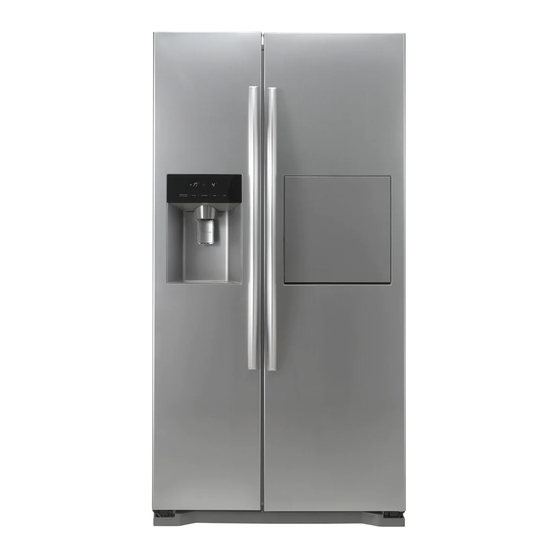
Summary of Contents for LG GR-P227
- Page 1 REFRIGERATOR SERVICE MANUAL CAUTION PLEASE READ CAREFULLY THE SAFETY PRECAUTIONS OF THIS BOOK BEFORE CHECKING OR OPERATING THE REFRIGERATOR. MODEL: GR-P227/L227 COLOR: TITANIUM...
-
Page 2: Table Of Contents
CONTENTS WARNINGS AND PRECAUTIONS FOR SAFETY ........................ 3 SPECIFICATIONS................................... 4 PARTS IDENTIFICATION ............................... 6 HOW TO INSTALL THE REFRIGERATOR .......................... 10 HOW TO ADJUST DOOR HEIGHT OF THE REFRIGERATOR ..................10 HOW TO INSTALL WATER PIPE ............................11 HOW TO CONTROL THE AMOUNT OF WATER SUPPLIED TO THE ICEMAKER ............15 MICOM FUNCTION ................................ -
Page 3: Warnings And Precautions For Safety
WARNINGS AND PRECAUTIONS FOR SAFETY Please observe the following safety precautions in order to 8. Do not fray, damage, machine, heavily bend, pull out, use safely and correctly the refrigerator and to prevent or twist the power cord. accident and danger during repair. 9. -
Page 4: Specifications
SPECIFICATIONS 1. Ref No. : GR-P227 ITEMS SPECIFICATIONS ITEMS SPECIFICATIONS DIMENSIONS (mm) 894(W) 790(D) 1753(H) FIRST DEFROST 4 - 5 Hours NET WEIGHT (kg) DEFROST CYCLE 13 - 15 Hours COOLING SYSTEM Fan Cooling DEFROSTING DEVICE Heater, Sheath TEMPERATURE CONTROL... - Page 5 SPECIFICATIONS 2. Ref No. : GR-L227 ITEMS SPECIFICATIONS ITEMS SPECIFICATIONS DIMENSIONS (mm) 894(W) 790(D) 1753(H) DRIER MOLECULAR SIEVE XH-7 NET WEIGHT (kg) FIRST DEFROST 4 - 5 Hours COOLING SYSTEM Fan Cooling DEFROST CYCLE 13 - 15 Hours TEMPERATURE CONTROL Micom Control DEFROSTING DEVICE Heater, Sheath...
-
Page 6: Parts Identification
PARTS IDENTIFICATION 1. Ref No. : GR-P227 /P257 (INTERNAL FILTER) o er rame i ater u e er am ater er utto ome ar Freezer e r erator compartment compartment i k ro uct cor er Automatic Icemaker oor ack... - Page 7 PARTS IDENTIFICATION 2. Ref No. : GR-P227 /P257 (EXTERNAL FILTER) o er rame i er am ater er utto ome ar Freezer e r erator compartment compartment i k ro uct cor er Automatic Icemaker oor ack er er tio a...
- Page 8 PARTS IDENTIFICATION 3. Ref No. : GR-L227 /P257 (INTERNAL FILTER) o er rame i ater u e er am ater er utto Freezer e r erator compartment compartment i k ro uct cor er Automatic Icemaker oor ack er er tio a i e o er a tic or ire...
- Page 9 PARTS IDENTIFICATION 4. Ref No. : GR-L227 /P257 (EXTERNAL FILTER) o er rame i er am ater er utto Freezer e r erator compartment compartment i k ro uct cor er Automatic Icemaker oor ack er er tio a i e o er a tic or ire e re me t ce ter tio a...
-
Page 10: How To Install The Refrigerator
HOW TO INSTALL REFRIGERATOR 1. How to Adjust Door Height of Refrigerator Make the refrigerator level first. (If the refrigerator is not installed on the flat floor, the height of freezer and refrigerator door may not be the same.) 1. If the height of freezer door is lower than that of 2. -
Page 11: How To Install Water Pipe
HOW TO INSTALL REFRIGERATOR 2. How to Install Water Pipe 2-1. When connecting directly to the water tap. Please confirm the following installation parts. Before Installation 1. The icemaker requires the water pressure of 1.5 - 8.5kgf/cm . (It is acceptable if city water fills a cup of 180cc with water for 3 seconds) 2. - Page 12 HOW TO INSTALL REFRIGERATOR 1. Connection of Pipe Connector A and B. Caution : • Feed pipe should be connected to cold water line. If it is connected to hot water line, trouble 1) Turn off main valve of water pipe. may occur.
- Page 13 HOW TO INSTALL REFRIGERATOR 3. When customer uses bottled water. *If customer wants to use bottled water, extra pump should be installed as shown below. 1. The pump system should not be on the floor (it may cause noise and vibration). Securely fasten the inlet and outlet nuts of pump.
- Page 14 HOW TO INSTALL REFRIGERATOR Install Water Filter (Applicable to some models only) Control box Before Installing water filter 1. Before installing the filter, take out the top shelf of the refrigerator after tilting it to the direction ( ) and lifting it to the direction ( ) and move it to the lower part.
-
Page 15: How To Control The Amount Of Water Supplied To The Icemaker
HOW TO INSTALL REFRIGERATOR 3. How to Control the Amount of Water Supplied to Icemaker. 3-1. Confirm the amount of water supplied to the icemaker. 1. Remove the cover bucket : Lift the cover with a slight twisting. 2. Remove the ice bucket : Lift the lower part slightly and take the ice bucket out slowly. •... - Page 16 HOW TO INSTALL REFRIGERATOR 3-2. Control the amount of water supplied to the icemaker. Caution : • Please unplug the power cord from the wall outlet and wait for more than three minutes before disconnecting PCB cover as 310V is applied in the control panel. (+) Driver 1.
-
Page 17: Micom Function
MICOM FUNCTION 1. Monitor Panel 1-1. GR-P227 Expres Freezer Door Alarm Button/ Selection Button Lock Button Dispenser Dispenser Light On/Off Button/ Selection Button Filter Status Display RESET Button Temperature Adjust Button Temperature Adjust Button For Freezer Compartment For Refrigerator Compartment 1-2. - Page 18 MICOM FUNCTION Once the mode activates, the display is always OFF. Until door is opened or display button is pressed. When 20 seconds has elapsed after closing door or pressing button, the display turns OFF. To deactivate this mode is same as the activation methods.
- Page 19 MICOM FUNCTION 2-1-2. LCD Back Light Control 1. In order to easily view display status on the LCD, LCD Back Light is turned on for a minute in application of initial power, for a minute in button manipulation and for a minute after closing time from opening time of door. 2.
- Page 20 MICOM FUNCTION 2-2. Dispenser use selection You can select water or ice. DISPENSER Please select water, slice ice and square ice by pressing button as you desire. Please press the push button lightly by catching and pushing in cup. • The border line is indicated for the selected function. •...
- Page 21 MICOM FUNCTION 2-7. Super freezing 1. EXPRESS FRZ freezing is a function to increase the cooling speed of the freezer compartment by running both the compressor and the fan simultaneously. 2.EXPRESS FRZ is cancelled and the refrigerator returns to its default setting in the event of a power interruption. 3.
- Page 22 MICOM FUNCTION 2-10. Control of M/C room fan motor 1. The M/C room fan motor performs ON/OFF control by linking with the COMP. 2. It controls at the single RPM without varying RPM. 3. Failure sensing method is same as in fan motor of freezing fan motor (refer to failure diagnosis function table for failure display).
- Page 23 MICOM FUNCTION 2-15. Sequential operation of built-in product Built-in products such as compressor, frost removal heater, freezing room fan, Cooling Fan and step motor damper are sequentially operated as follows for preventing noise and part damage occurred due to simultaneous operation of a lot of parts in applying initial power and completing test.
- Page 24 MICOM FUNCTION 2-16. Failure Diagnosis Function 1. Failure diagnosis function is function to facilitate service when nonconforming matters affecting performance of product during use of product. 2. In occurrence of failure, pressing the function adjustment button does not perform function. 3.
- Page 25 MICOM FUNCTION 2-17. Test Function 1. The purpose of test function is to check function of the PWB and product and to search for the failure part at the failure status. 2. Test button is placed on the main PCB of refrigerator (test switch), and the test mode will be finished after maximum 2 hours irrespective of test mode and then is reset to the normal status.
- Page 26 MICOM FUNCTION LCD check function: If simultaneously pressing super freezer button and freezing temperature adjustment button for a second, a back light is turned on and all display LCD graphics on. If releasing the button, the LCD graphic displays the previous status, the back light is turned off (LCD graphic and back light ON/OFF check).
-
Page 27: Explation For Micom Circuit
Caution : Since high voltage (310 Vdc) is maintained at the power terminal, wait at least 3 minutes after unplugging the appliance to check the voltages to allow the current to dissipate. Voltage of every part is as follows: Part Voltage 230 Vac inspection Vdc 13~16 Vdc 12 Vdc 15.5 Vdc 5 Vdc (1) GR-P227/L227 - 27 -... - Page 28 MICOM (IC1). The oscillator (OSC1) must always be replaced with an exact replacement part. If this specification is changed, the change will affect the time calculations of the MICOM and it might not work at all. (1) GR-P227/L227 1-3. Reset circuit The RESET circuit allows various parts of the MICOM, such as RAM, defrosting, etc., to be restarted from the initial state...
- Page 29 Frost Dispenser AC Converting Type of Load COMP Removal R-room LAMP Pipe Heater Relay Heater Heater Measuring part (IC6) No.16 No.12 No.11 No.15 No.13 No.14 Within 1 V Status 12 V (1) GR-P227/L227 - 29 -...
- Page 30 EXPLATION FOR MICOM CIRCUIT 1-5. Dispenser operation circuit (1) GR-P227/L227 1) Check load driving status WATER VALVE GEARED SOLENOID PILOT SOLENOID HOME BAR Type of Load MOTOR CUBE VALVE DISPENSER HEATER WATER Measuring part IC7-No.16 IC7-No.15 IC7-No.14 IC7-No.13 IC7-No.12 IC7-No.11 IC7-No.10...
- Page 31 EXPLATION FOR MICOM CIRCUIT 1-6. Door opening sensing circuit (1) GR-P227/L227 Measuring part IC1 (MICOM) No. 47, 46 Pin Door of Freezing/Cold Storage Room Closing 5 V ( A - B , C - D, E - F . S/W at both ends are at Off status) Opening 5 V ( A - B , C - D, E - F .
- Page 32 EXPLATION FOR MICOM CIRCUIT 1-7. Temperature sensing circuit (1) GR-P227/L227 The above circuits are circuits attached to freezing room sensor or cold storage room sensor for adjusting setting temperature at the freezing room and cold storage room, ice-making sensor for sensing water temperature in ice-making, or an evaporator for sensing temperature of a frost removal sensor necessary for frost removal.
- Page 33 EXPLATION FOR MICOM CIRCUIT 1-8. Switch entry circuit The following circuits are sensing signal form the damper motor reed switch for testing and diagnosing the refrigerator. (1) GR-P227/L227 1-9. Option designation circuit (model separation function) (1) GR-P227/L227 The circuits shown above vary according to which features are included on your particular model.
- Page 34 EXPLATION FOR MICOM CIRCUIT 1-10. Stepping motor operation circuit (1) GR-P227/L227 The motor is driven by magnetism formed in the areas of the coils and the stator. Rotation begins when a HIGH signal is applied to MICOM Pin 33 of IC10 (TA7774F). This causes an output of HIGH and LOW signals on MICOM pins 34 and 35.
- Page 35 3. This circuit stops the fan motor by cutting off power to the fan when it senses a lock-up condition. a , d part b part e part Motor OFF 2V or less 2V or less Motor ON 2 ~ 3V 12 ~ 14V 8 ~ 16V (1) GR-P227/L227 - 35 -...
- Page 36 EXPLATION FOR MICOM CIRCUIT 1-12. Temperature compensation and temperature compensation circuit 1. Temperature compensation in freezer and refrigerator (1) GR-P227/L227 : JUMP WIRE Freezing room Cold storage room Resistance value Temperature Resistance value Temperature Remarks compensation (RCR1) compensation (R)J1 (R)J2 6.2 kΩ...
- Page 37 EXPLATION FOR MICOM CIRCUIT u Temperature compensation table at the refrigerator is as follows: Modification resistance 470 Ω 2 kΩ 3.3 kΩ 5.6 kΩ 8.2 kΩ 10 kΩ 12 kΩ 18 kΩ 33 kΩ 56 kΩ 180 kΩ Current resistance 0.5 °C 1 °C 1.5 °C...
- Page 38 EXPLATION FOR MICOM CIRCUIT 2. Compensation circuit for temperature at freezer (1) GR-P227/L227 Temperature compensation in CUT JCR1 +1 °C [+1.8 °F] +2 °C [+3.6 °F] JCR2 +1 °C [+1.8 °F] JCR3 -1 °C [-1.8 °F] -2 °C [-3.6 °F] JCR4 -1 °C [-1.8 °F]...
- Page 39 MICOM of main PCB and LCD (LED) dedicated MICOM for LCD (LED) control of display PCB. Main PCB L/Wire FD/H(4-wires) Display PCB DC 12V Main MICOM LCD(LED) dedicated MICOM Transmission (error status) Reception (notch status) (1) GR-P227/L227 - 39 -...
- Page 40 EXPLATION FOR MICOM CIRCUIT 2) Sensor resistance characteristics table Refrigerator sensor 1&2 Measuring Temperature (°C) Freezing Sensor Defrost sensor, Ambient sensor -20 °C 22.3 kΩ 77 kΩ -15 °C 16.9 kΩ 60 kΩ -15 °C 13.0 kΩ 47.3 kΩ -5 °C 10.1 kΩ...
- Page 41 EXPLATION FOR MICOM CIRCUIT 1-14. Miracle Zone STEPPING MOTOR / Display Miracle zone stepping motor damper is same as 1-8 stepping motor operation circuit and the miracle zone display turns on only when the R-door opens. - 41 -...
-
Page 42: Icemaker And Dispenser Working Principles And Repair
1-2. Dispenser Working Principles 1. This function is available in Model GR-P227/257S, GR-L227/257S where water and ice are available without opening freezer compartment door. 2. “Crushed Ice” is automatically selected when power is initially applied or reapplied after power cut. -
Page 43: Functions Of Ice Maker
ICE MAKER AND DISPENSER WORKING PRINCIPLES AND REPAIR 2. Function of Ice Maker 2-1. Initial Control Function 1. When power is initially applied or reapplied after power cut, it detects level of ice maker cube mould after completion of MICOM initialization. The detecting lever moves up and down. 2. -
Page 44: Ice Ejection Control Function
ICE MAKER AND DISPENSER WORKING PRINCIPLES AND REPAIR 2-4. Ice Ejection Control Function 1. This is to eject ice from ice maker cube mould after ice making is completed. 2. If Hall IC signal is on within 3.6 seconds after ice ejection motor rotates in normal direction, it does not proceed ice ejection but waits. - Page 45 ICE MAKER AND DISPENSER WORKING PRINCIPLES AND REPAIR 2-5 Test Function 1. It is to force the operation during operation test, service, and cleaning. The test switch is mounted under the automatic ice maker. The test function starts when the test switch is pressed for more than 0.5 second. 2.
- Page 46 * Troubleshooting: it is possible to confirm by pressing freezer and refrigerator temperature control buttons for more than 1 second. (ice maker is normal if all leds are on): refer to trouble diagnposis function in MICOM function 2-8 (page 18) <GR-P227/257S, GR-L227/257S: 88-LED> Is DC Power (5V and 12V) Failed DC Power...
- Page 47 ICE MAKER AND DISPENSER WORKING PRINCIPLES AND REPAIR <GR-P227/257S, GR-L227/257S: Bar-LED> Is DC Power (5V and 12V) Failed DC Power Change main PWB output normal? • Check DC power (5V, 12V). Is cube ice led off during Replace Ice making...
-
Page 48: Circuit
CIRCUIT (1) GR-P227/L227 - 48 -... -
Page 49: Trouble Diagnosis
TROUBLE DIAGNOSIS 1. Trouble Shooting CLAIMS. CAUSES AND CHECK POINTS. HOW TO CHECK * Measuring instrument : 1) No power on outlet. 1. Faulty start Multi tester 2) No power on cord. Bad connection between adapter and outlet. (faulty adapter) Check the voltage. - Page 50 TROUBLE DIAGNOSIS CLAIMS. CAUSES AND CHECK POINTS. HOW TO CHECK 2. No cooling. Check the clogged 2) Refrigeration system is clogged. evaporator by heating (as Moisture Residual moisture Air Blowing. Not performed. soon as the cracking sound clogged. in the evaporator. Too short.
- Page 51 TROUBLE DIAGNOSIS CLAIMS. CAUSES AND CHECK POINTS. HOW TO CHECK 3. Refrigeration 1) Refrigerant Partly leaked. Weld joint leak. is weak. Parts leak. 2) Poor defrosting capacity. Check visually. Drain path (pipe) clogged. Inject P/U into drain hose. Inject through the hole.
- Page 52 TROUBLE DIAGNOSIS CLAIMS. CAUSES AND CHECK POINTS. HOW TO CHECK 3. Refrigeration Residual Weak heat from heater. Sheath Heater - rated. is weak. frost. Heater plate - rated. Too short defrosting time. Defrost Sensor. - Faulty characteristics. Seat-D(missing, location. thickness). Structural fault.
- Page 53 TROUBLE DIAGNOSIS CLAIMS. CAUSES AND CHECK POINTS. HOW TO CHECK 3. Refrigeration 4) No cooling air circulation. is weak. Faulty fan motor. Fan is Fan shroud contact. - Clearance. constrained. Damping evaporator contact. Accumulated residual frost. Small cooling air Insufficient Fan overload.
- Page 54 TROUBLE DIAGNOSIS CLAIMS. CAUSES AND CHECK POINTS. HOW TO CHECK 4. Warm 1) Colgged cooling path. refrigerator P/U liquid leak. compartment Foreign materials. –– P/U dump liquid. temperature. 2) Food storate. Store hot food. Store too much at once. Door open. Packages block air flow.
- Page 55 TROUBLE DIAGNOSIS CLAIMS. CAUSES AND CHECK POINTS. HOW TO CHECK 6. Dew and 4) Dew on door. ice formation. Dew on the duct door. - Duct door heater is cut. Dew on the dispense Recess Heater is cut. recess. Duct door is open. / Foreign material clogging. Dew on the door surface.
- Page 56 TROUBLE DIAGNOSIS CLAIMS. CAUSES AND CHECK POINTS. HOW TO CHECK 7. Sounds 1) Compressor compartment operating sounds. Transformer sound. Its own fault. –– Core gap. Bad connection. –– Correct screw connection. Drip tray vibration sound. Bad assembly. Distortion. Foreign materials inside. Back cover machine sound.
- Page 57 TROUBLE DIAGNOSIS CLAIMS. CAUSES AND CHECK POINTS. HOW TO CHECK 8. Faulty lamp 1) Lamp problem. Filament blows out. (freezer and Glass is broken. refrigerator 2) Bad lamp assembly. Not inserted. compartment). Loosened by vibration. 3) Bad lamp socket. Disconnection. Bad soldering.
- Page 58 TROUBLE DIAGNOSIS CLAIMS. CAUSES AND CHECK POINTS. HOW TO CHECK 10. Structure, 1) Door foam. appearance Sag. Weak torque of Bolt is loosened during and others. hinge connection. transportaion. Not tightly fastened. Screw worn out . Weak gasket Adhesion surface. adhesion.
-
Page 59: Faults
TROUBLE DIAGNOSIS - 59 -... - Page 60 TROUBLE DIAGNOSIS - 60 -...
- Page 61 TROUBLE DIAGNOSIS - 61 -...
- Page 62 TROUBLE DIAGNOSIS - 62 -...
- Page 63 TROUBLE DIAGNOSIS - 63 -...
- Page 64 TROUBLE DIAGNOSIS - 64 -...
- Page 65 TROUBLE DIAGNOSIS - 65 -...
- Page 66 TROUBLE DIAGNOSIS - 66 -...
- Page 67 TROUBLE DIAGNOSIS - 67 -...
- Page 68 TROUBLE DIAGNOSIS - 68 -...
- Page 69 TROUBLE DIAGNOSIS - 69 -...
- Page 70 TROUBLE DIAGNOSIS - 70 -...
- Page 71 TROUBLE DIAGNOSIS - 71 -...
- Page 72 TROUBLE DIAGNOSIS - 72 -...
- Page 73 TROUBLE DIAGNOSIS - 73 -...
- Page 74 TROUBLE DIAGNOSIS - 74 -...
- Page 75 TROUBLE DIAGNOSIS - 75 -...
-
Page 76: Cooling Cycle Heavy Repair
TROUBLE DIAGNOSIS 3. Cooling Cycle Heavy Repair 3-1. The Heavy Repair Standards for Refrigerator with R134a Refrigerant Items Unit Standards Purposes Remarks Pipe and piping Min. Pipe:within 1 hour. To protect The opening time should be reduced to a system opening time. Comp:within Moisture half of the standards during rain and... - Page 77 TROUBLE DIAGNOSIS 3-2. Summary Of Heavy Repair Process Contents Tools Trouble diagnosis Remove refrigerant - Cut charging pipe ends and discharge refrigerant from Filter, side cutters Residuals drier and compressor. - Use R134a oil and refrigerant for compressor and drier Pipe Cutter, Gas welder, N - Confirm N sealing and packing conditions before use.
- Page 78 TROUBLE DIAGNOSIS 3-3. Precautions During Heavy Repair Items Precautions 1. Use of tools. 1) Use special parts and tools for R134a. 2. Removal of retained 1) Remove retained refrigerant more than 5 minutes after turning off a refrigerator. refrigerant. (If not, oil will leak inside.) 2) Remove retained refrigerant by cutting first high pressure side (drier part) with a nipper and then cut low pressure side.
- Page 79 TROUBLE DIAGNOSIS 3-4. Practical Work For Heavy Repair Items Precautions 1. Removal of residual Evaporator Low pressure side refrigerant. KEYPOINTING Observe the sequence for Compressor removal of refrigerant. Drier (If not, compressor oil may Suction leak.) High pressure side Release Condenser Refrigent Intake...
- Page 80 TROUBLE DIAGNOSIS Items Precautions 4.Vacuum degassing. Evaporator Suction pipe Compressor Drier Condenser pressure High Blue pressure Yellow Vaccum KEYPOINTING Pump - If power is applied during vacuum degassing, vacuum degassing shall be more effective. Pipe Connection - Operate compressor Connect a red hose to the high pressure side and a blue hose to the while charging refrigerant.
- Page 81 TROUBLE DIAGNOSIS Items Precautions Evaporator Compressor Drier Condenser Bombe 4) Refrigerant Charging Charge refrigerant while operating a compressor as shown above. 5) Pinch a charging pipe with a pinch-off plier after completion of charging. 6) Braze the end of a pinched charging pipe with copper brazer and take a gas leakage test on the welded parts.
- Page 82 TROUBLE DIAGNOSIS 3-6. Brazing Reference Drawings 1) Asia / Middle-East Africa PIPE ASSEMBLY HOT LINE PIPE ASSEMBLY HOT LINE (Refrigerator) (Freezer) Copper(Silver) Copper Brazer Brazer CAPI - TUBE DRIER ASSEMBLY Copper(Silver) Silver Brazer Brazer PIPE ASSEMBLY PIPE ASSEMBLY JOINT SUCTION Copper Brazer PIPE ASSEMBLY...
-
Page 83: How To Deal With Claims
TROUBLE DIAGNOSIS 4. HOW TO DEAL WITH CLAIMS 4-1. Sound Problems Checks and Measures "Whizz" sounds Explain general principles of sounds. • All refrigerator when functioning properly have normal operating sound. The compressor and fan produce sounds. There is a fan in the freezer compartment which blows cool air to freezer and refrigerator compartments. - Page 84 TROUBLE DIAGNOSIS Problems Checks and Measures Sounds of water flowing Explain the flow of refrigerant. • When the refrigerator stops, the water flowing sound happens. This sound happens when the liquid or vapor refrigerant flows from the evaporator to compressor. "Click"...
- Page 85 TROUBLE DIAGNOSIS 4-2. Measures for Symptoms on Temperature Problems Checks and Measures Refrigeration is weak. Check temperature set in the temperature control knob. • Refrigerator is generally delivered with the button set at “normal use” (MID). But customer can adjust the temperature set depending on their habit and taste. If you feel the refrigeration is weak, then set the temperature control button at “strong”...
- Page 86 TROUBLE DIAGNOSIS 4-3. Odor and Frost Problems Checks and Measures Odor in the refrigerator compartment. Explain the basic principles of food odor. • Each food has its own peculiar odor. Therefore it is impossible to prevent or avoid food odor completely when food is stored in the completely sealed refrigerator compartment.
- Page 87 TROUBLE DIAGNOSIS 4-5. Others Problems Checks and Measures The refrigerator case is hot. Explain the principles of radiator. • The radiator pipes are installed in the refrigerator case and partition plate between the refrigerator and the freezer compartment in order to prevent condensation formation.
-
Page 88: How To Disassemble And Assemble
HOW TO DISASSEMBLE AND ASSEMBLE 1. DOOR (3) Disconnect upper hinge from a hinge supporter by grasping the front part of upper hinge and lifting up (Hinge Assembly, U) in arrow direction A and pull 1) Remove lower cover and then disconnect water forward in arrow B direction. -
Page 89: Handle
HOW TO DISASSEMBLE AND ASSEMBLE 2. HANDLE 3. SHROUD, GRILLE FAN 1) Put blade screwdriver into a groove on the side of a 1) Loosen two screws after disconnecting a cap screw of a Deco handle and lift up a little bit in arrow direction grille fan(U) with a balde screwdriver. -
Page 90: Water Valve Disassembly Method
HOW TO DISASSEMBLE AND ASSEMBLE 4. WATER VALVE DISASSEMBLY 4). Separate the Mechanical Cover and Valve Screw. METHOD Mechanical Cover 1) Turn off the power of the refrigerator (pull out the plug). Open the FREEZER and REFRIGERATOR Door and disassemble the Lower Cover. 5) Separate the housing and pull out the valve. -
Page 91: Dispenser
HOW TO DISASSEMBLE AND ASSEMBLE 6. DISPENSER 4) Loosen four screws with a phillips screwdriver and pull the funnel assembly to disconnect. 1) Disconnect funnel and button assembly by pulling down and forward. Funnel Assembly Funnel Assembly Button 5) The duct cap assembly can be disconnected if the hold lever connecting screw is loosened with a phillips driver. - Page 92 HOW TO DISASSEMBLE AND ASSEMBLE 7) Dispenser Related Parts FRAME ASSEMBLY, DISPLAY COVER, DISPENSER DECO, FRAME DISPLAY PWB(PCB) ASSEMBLY, DISPLAY FUNNEL ASSEMBLY MICRO SWITCH FRAME, FUNNEL 10 LEVER(SWITCH) 11 FUNNEL 12 BUTTON LEVER 13 HOLLDER BUTTON 14 SOLENOID ASSEMBLY 15 SPRING 16 LEVER HOLDER 17 CAP ASSEMBLY, DUCT 18 CAP, DUCT...
-
Page 93: Exploded View
EXPLODED VIEW FREEZER DOOR PART: GR-P227/P257/L227/L257 200A 612A 611B 202A 606A 600A 610A 205C 614A 205B 205A 210B 205D 210B 210B 201A 203A - 94 -... - Page 94 EXPLODED VIEW Ref No. : GR-L227, GR-L257 REFRIGERATOR DOOR PART : Optional part 241A 230A 241C 241B 232A 212G 243A 240A 205C 243A 205B 205A 240A 205D 240C 240D 233A 231A 240E - 97 -...
-
Page 95: Freezer Compartment
EXPLODED VIEW FREEZER COMPARTMENT : Optional part 270A 101B 271B 271A 137B 137A 312B 136D 403A 136B 136C 312C 136A 135A 402A 152A 120D 128C 302B 130A 120D 128C 401A 128D 120B 128E 128D 400A 128F 120C 621A 623B 125A 621B 316B 272A... -
Page 96: Refrigerator Compartment
EXPLODED VIEW Ref No. : GR-L227/P227 REFRIGERATOR COMPARTMENT : Optional part 146B 625A 101A 270B 271B 146A 140A 271C 626C 626B 626A 115A 116A 140A 149E 115C 402A 140A 115B 151A 152A 624C 151C 151B 401A 166B 166B 177A 166C 166C 177B 162A... - Page 97 EXPLODED VIEW Ref No. : GR-L257/P257 REFRIGERATOR COMPARTMENT : Optional part 140A 101A 270B 140A 271B 146A 271C 626C 626B 140A 626A 171A 115A 141B 116A 115B 171B 402A 115C 151A 170A 152A 624C 151B 151C 401A 166B 177A 166C 177B 162A 155A...
- Page 98 EXPLODED VIEW ICE & WATER PART : Optional part 625A 624B 616F 616G 404A 627A 619A 620A 619A - 101 -...
- Page 99 EXPLODED VIEW MACHINE COMPARTMENT : Optional part 406A 502A 410H 303A 500A 303B 502B 304A 303C 313A 316A 300A 310B 307A 307A 317A 328A 317B 308B 403B 309B 309C 104A 309A 306A 308A 308C 305A 301A 305B 305C 310A 305C 305B - 102 -...
- Page 100 EXPLODED VIEW DISPENSER PART : Optional part 278A 278C 402C 278B 276A 275A 278F 405A 276B 501A 280A 279B 278D 600A 600A 602A 280B 605A 280C 604A 281A 601A 603B 603A 279A - 103 -...
- Page 101 P/No. 3828JD8966P October., 2008 Printed in Korea...
Need help?
Do you have a question about the GR-P227 and is the answer not in the manual?
Questions and answers