Sign In
Upload
Download
Table of Contents
Contents
Add to my manuals
Delete from my manuals
Share
URL of this page:
HTML Link:
Bookmark this page
Add
Manual will be automatically added to "My Manuals"
Print this page
×
Bookmark added
×
Added to my manuals
Manuals
Brands
LG Manuals
Refrigerator
GR-L258
Service manual
LG GR-L258 Service Manual
Hide thumbs
1
Table Of Contents
2
3
4
5
6
7
8
9
10
11
12
13
14
15
16
17
18
19
20
21
22
23
24
25
26
27
28
29
30
31
32
33
34
35
36
37
38
39
40
41
42
43
44
45
46
47
48
49
page
of
49
Go
/
49
Contents
Table of Contents
Troubleshooting
Bookmarks
Table of Contents
Safety Precautions
Table of Contents
1 Specifications
2 Parts Identification
3 Disassembly
Removing and Replacing Refrigerator Doors
Door
To Remove the Dispenser
Door Alignment
FAN and FAN MOTOR(Evaporator)
Ice Fan Scroll Assembly Replacement
Defrost Control Assembly
Lamp
Control Box-Refrigerator
Multi Duct
Main Pwb, Display Pwb Replacement, Funnel Replacement
Sub Pwb for Dispenser, Duct Door Replacement, Ice Corner Door Replacement, Ice Maker Assembly
Auger Motor Cover, Auger Motor Replacement
Door Ice bin
How to Remove and Reinstall the Pullout Drawer
4 Adjustment
Compressor
Ptc-Starter
Water Valve Disassembly Method
Fan and Fan Motor Disassembly Method
Olp(Overload Protector)
To Remove the Cover Ptc
5 Circuit Diagram
6 Troubleshooting
Compressor and Electric Components
Other Electrical Components
Service Diagnosis Chart
Refrigeration Cycle
7 Operation Principle & Repair Method of Icemaker
8 Description of Function, Circuits & Error Codes
ERROR CODE on Display Panel
9 Exploded View & Replacement Parts List
Door Parts
Advertisement
Quick Links
1
Specifications
2
Parts Identification
3
Circuit Diagram
4
Compressor and Electric Components
5
Exploded View & Replacement Parts List
Download this manual
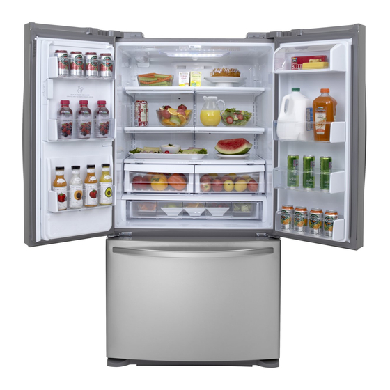
REFRIGERATOR
SERVICE MANUAL
CAUTION
BEFORE SERVICING THE UNIT,
READ THE SAFETY PRECAUTIONS IN THIS MANUAL.
MODEL: GR-L258
GR-L218
COLOR: TITANIUM
WESTERN BLACK
SUPER WHITE
STAINLESS
Table of
Contents
Previous
Page
Next
Page
1
2
3
4
5
Advertisement
Table of Contents
Need help?
Do you have a question about the GR-L258 and is the answer not in the manual?
Ask a question
Questions and answers
Related Manuals for LG GR-L258
Refrigerator LG GR-P227 Service Manual
Lg refrigerator service manual (100 pages)
Refrigerator LG GR-GR-L257BTBA Service Manual
Sxs refrigerator (128 pages)
Refrigerator LG GR-L258USJH Owner's Manual
Bottom freezer refrigerator (42 pages)
Refrigerator LG GR-L258USGH User Manual
Bottom freezer refrigerator (41 pages)
Refrigerator LG GR-L257STF User Manual
(30 pages)
Refrigerator LG GR-L258AUS Service Manual
Color: stainless st (52 pages)
Refrigerator LG LFX25971ST User's Manual & Installation Instructions
3-door french door refrigerator with ice and water dispenser (25 cu.ft.; stainless steel) (45 pages)
Refrigerator LG GR-B197WV Service Manual
(113 pages)
Refrigerator LG BOTTOM FREEZER REFRIGERATOR User Manual
(38 pages)
Refrigerator LG GR-P247C Service Manual
Refrigerator (66 pages)
Refrigerator LG BOTTOM FREEZER REFRIGERATOR Owner's Manual
(48 pages)
Refrigerator LG SxS GR-P247 Service Manual
(125 pages)
Refrigerator LG GR-B238J Series Owner's Manual
(32 pages)
Refrigerator LG GR-L219STSL User Manual
Bottom freezer refrigerator (44 pages)
Refrigerator LG GR-L207TQA User Manual
(28 pages)
Refrigerator LG GR-L207TTQ User Manual
(32 pages)
This manual is also suitable for:
Gr-l218
Table of Contents
Print
Rename the bookmark
Delete bookmark?
Delete from my manuals?
Login
Sign In
OR
Sign in with Facebook
Sign in with Google
Upload manual
Upload from disk
Upload from URL


Need help?
Do you have a question about the GR-L258 and is the answer not in the manual?
Questions and answers