
Related Manuals for Samsung MR7491G


Summary of Contents for Samsung MR7491G
-
Page 1: Table Of Contents
MICROWAVE OVEN MR7491G / MR7493G SERVICE Manual CONTENTS MICROWAVE OVEN 1. Precaution 2. Specifications 3. Operating Instructions 4. Disassembly and Reassembly 5. Alignment and Adjustments 6. Troubleshooting 7. Exploded Views and Parts List 8. PCB Diagrams 9. Schematic Diagrams... - Page 2 (e) A Microwave leakage check to verify compliance with the Federal performance standard should be performed on each oven prior to release to the owner. Samsung Electronics...
-
Page 3: Precaution
10. Service technicians should remove their 16. Always connect a test instrument's ground lead to the instrument chassis ground before watches while repairing an MWO. connecting the positive lead; always remove the instrument's ground lead last. Samsung Electronics... - Page 4 PRECAUTION with the oven energized. DO NOT measure the voltage in the high voltage circuit Servicemen should remove their watches whenever including filament voltage of magnetron. working close to or replacing the magnetron. Samsung Electronics...
-
Page 5: Specifications
2. Specifications 2-1 Table of Specifications MODEL MR7491G / MR7493G ITEM TIMER 99 MINUTES 99 SECONDS POWER SOURCE 120V/60HZ, AC POWER CONSUMPTION MICROWAVE : 1,450W OUTPUT POWER FROM 100W TO 1000W (10 LEVEL POWER) (IEC-705 TEST PROCEDURE) OPERATING FREQUENCY 2,450MHz... -
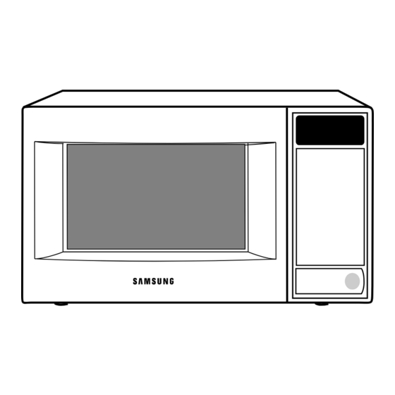
Page 6: Operating Instructions
Press to pause oven or correct a mistake. Press to start cooking. 3-2 Features & External Views Ventilation Holes Light Door Safety Interlock Holes Control Panel Door Latches Open Door Push Button Guide Roller Glass Plate 270mm 410mm 556mm 448mm Samsung Electronics... -
Page 7: Disassembly And Reassembly
4-2 Replacement of High Voltage Transformer 1. Discharge the high voltage capacitor. 2. Disconnect all the leads. 3. Remove the mounting bolts. 4. Reconnect the leads correctly and firmly. Bolts H. V. Trans Samsung Electronics... - Page 8 ¥ Insertion depth of the thin metal plate should be 0.5mm or less. 4-3-3 Removal of Key Door & Spring Door "E" Remove pin hinge from Door "E" Detach spring from Door "E" and key door. Key Door Spring Samsung Electronics...
- Page 9 7. When replacing the drive motor, be sure to remount it in the correct position with the coupler. 8. Connect all the leads to the drive motor. Drive Motor Cover Base Plate 9. Screw the drive motor cover to the base plate with a screw driver. Samsung Electronics...
- Page 10 3. When installing new membrane key board, make sure that the surface of escutcheon base is Membrane cleaned sufficiently so that any problems Panel (shorted contacts or uneven surface) can be avoided. Samsung Electronics...
-
Page 11: Alignment And Adjustments
2. Isolate the magnetron from the circuit by disconnecting its leads. 3. A continuity check across the magnetron filament terminals should indicate one ohm or less. 4. A continuity check between each filament terminal and magnetron case should read open. Cooling Fins Samsung Electronics... - Page 12 ¥ Primary switch ¥ Secondary switch 5. Confirm that the gap between the switch ¥ Monitor switch (COM-NC) housing and the switch actuator is no more than ¥ Door Sensing S/W 0.5mm when door is closed. Samsung Electronics...
- Page 13 5. After heating for 2 minutes, measure the water temperature in each beaker. 6. Microwave heat distribution rate can be calculated as follows: Minimum Beaker Temperature Rise Heat Distribution = X 100(%) Maximum Temperature Rise The result should exceed 65%. Cooking Tray Samsung Electronics...
- Page 14 ; CENTRAL SERVICE CENTER 5-13-2 At least once a year have the microwave energy survey meter checked for accuracy by its manufacturer. Samsung Electronics...
-
Page 15: Troubleshooting
H.V.Transformer component test procedure and replace if it is H.V.Capacitor defective. H.V.Diode Magnetron 4. Open or loose wiring of power relay 5. Defective primary latch switch 6. Defective power relay or Ass'y PCB Replace PCB main. Samsung Electronics... - Page 16 Use plastic wrap or cover with a lid. Stir once or twice while cooking foods such as soup, cocoa, or milk. Noise from the turntable motor Noise may result from the motor. Replace turntable motor. when it starts to operate. Samsung Electronics...
-
Page 17: Exploded Views And Parts List
7. Exploded Views and Parts List 7-1 Exploded Views Samsung Electronics... - Page 18 DE59-40001A DIODE-H.V HVR-1X-32B-12 DE74-20002A TRAY-COOKING GLASS,T6,PI360,1.2CUFT,NEG DE97-00009A ASSY-GUIDE ROLLER MW7896W,D16.5,BLK,XARAC DE67-60082A COUPLER PPS,T5.3XL24.1,-,BRN,3RD-W(1.3),MW7896W DE61-50574A BRACKET-TCO SECC/SPP,T0.6,-,-,-,3RD-1.3 MW7896W DE80-10002E BASE-PLATE SGCC,T0.8,W404,L633,MR7491G,NO-HINGE/HOLE DE31-10154A MOTOR-DRIVE M2HJ49ZR02,ST-16,50/60HZ,- DE71-60449A COVER-MGT PP(TB53),-,25G,110.5X115,GE-WHT,3RD-1.3 MW789 DE93-30375V ASSY CONTROL-BOX MR7491G,-,R/V MR7491G DE93-30375W ASSY CONTROL-BOX MR7493G,-,R/V MR7493G DE92-40176H ASSY DOOR MW7491G,GRAY,3RD-1.3,NEW GUARD...
- Page 19 PP(TB53),T1.5,BLK,1.2CU.FT,M24 7-4 Control Parts List Ref. No. Parts No. Description Specification Q'ty Remarks DE66-20010B BUTTON-PUSH ABS,D-GRY,17.6G,MW4371G DE61-70076A SPRING-BUTTON HSWR,PI0.6 DE34-10207V SWITCH-MEMBRANE PET,MR7491G,-,-,-,-,-,100W,SEA,WHT MR7491G DE34-10207W SWITCH-MEMBRANE PET,MR7493G,-,-,-,-,-,100W,SEA,WHT MR7493G DE72-70162B CONTROL-PANEL ABS,250G,D/GRY,T2.5,MW6371G,-, DE67-40003A WINDOW-DISPLAY ACRYL,T2.3,W36.8,L91.8,SMOG,MW RA-W3USA-00 ASSY PCB-MAIN DE93-30405F ASSY CONTROL-PANEL MW6371G 7-5 Body Latch Parts List Ref.
- Page 20 DE60-10082J SCREW-TAPPING TH,2S-4X8,MSWR3,ZPC,YEL,WS A/DUCT DE60-10098A SCREW-ASSY TAP TITE PH,TC,M4X8,SWRCH18A,ZPC2,GLD,W M/DRIV DE60-10195A SCREW-STAR POLE TH,*,2,4,12,SWCH18A,ZNC O/PANEL DE92-90522A ASSY-SCREW PACK MR5481G,SCREW-A(6EA) MR7491G DE60-10088A SCREW-TAP PH PH,M3,L8,FEFZY,PLAIN DE60-10012A SCREW-TAP TITE TH,+,3,M4,L10,SWR10,ZPC2,TOOTH DE60-10082H SCREW-A 2S-4X12,TOOTHED 7-7 Installation Instructions Ref. No. Parts No. Description Specification...
- Page 21 8. P.C.B Diagrams 8-1 P.C.B Diagrams Samsung Electronics...
- Page 22 4MHz,0.5%,TP,10.0x5.0x7.5mm XTL1 P35 3711-000940 CONNECTOR-HEADER BOX,4P,1R,2.5mm,STRAIGHT,SN CN03 P36 3711-004143 CONNECTOR-HEADER BOX,2P/3P,1R,5mm/2.5mm,STRAIGH CN07 P37 DE13-20009A KA7533,DIP IC02 P38 DE39-60001A WIRE-SO COPPER PI0.6,SN,T,52MM,TAPING_WIRE J01,J02,J04,J05,J10 P38 DE39-60001A WIRE-SO COPPER PI0.6,SN,T,52MM,TAPING_WIRE J11,J12,J13,J14,J15 P38 DE39-60001A WIRE-SO COPPER PI0.6,SN,T,52MM,TAPING_WIRE P39 DE09-00032A IC-MCU HCD6433724-F18,MW5693W(3RD-VFD),8BIT IC01 Samsung Electronics...
-
Page 23: Schematic Diagrams
BLK BLK BLU RED : BLUE ORG : GRANGE BLK BLU : GREEN : RED SECONDARY PRIMARY INTERLOCK DOOR INTERLOCK SWITCH INTERLOCK SWITCH SENSING SWITCH MONITOR SWITCH MAGNETRON HIGH VOLTAGE DIODE TO CHASSIS HIGH VOLTAGE CAPACITOR HIGH VOLTAGE TRANSFORMER Samsung Electronics...
Need help?
Do you have a question about the MR7491G and is the answer not in the manual?
Questions and answers