Table of Contents
Advertisement
Advertisement
Table of Contents

Subscribe to Our Youtube Channel
Related Manuals for laguna MJOIN 8020-0130


Summary of Contents for laguna MJOIN 8020-0130
- Page 1 8" Jointer Parallelogram Manual LAGUNA TOOLS 2072 Alton Parkway Irvine, California 92606 Ph: 800.234.1976 Model Number: MJOIN 8020-0130 www.lagunatools.com © 2018, Laguna Tools, Inc. LAGUNA® and the LAGUNA Logo® are the registered trademarks of Laguna Tools, Inc. All rights reserved.
-
Page 3: Table Of Contents
contents Table of Page number Safety Rules Warranty Noise emission Specification sheet Receiving your jointer Introduction to your jointer What you receive with jointer Parts of the jointer Where to locate your jointer Unpacking your jointer Assembly and set up Running &... -
Page 4: Safety Rules
Safety Rules As with all machinery there are certain hazards involved with the operation and use. Using it with caution will considerably lessen the possibility of personal injury. However, if normal safety precautions are overlooked or ignored, personal injury to the operator may result. If you have any questions relative to the installation and operation, do not use the equipment until you have contacted your supplying distributor. -
Page 5: Warranty
Machines sold through dealers must be registered with Laguna Tools within 30 days of purchase to be covered by this warranty. Laguna Tools guarantees all new machines and accessories sold to be free of manufacturers’... -
Page 6: Noise Emission
All damage must be noted on the delivery documents and signed by you, and the delivery driver. You must then contact the seller, [Laguna Tools] within 24 hours. Introduction to jointer. The jointer is designed to give you years of safe service. Read this owner’s manual in its entirety before assembly or use. -
Page 7: What You Receive With Jointer
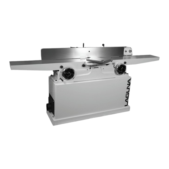
2. Cutter head alignment. To reduce the possibility of kickback, keep the top edge of the out feed table aligned with the cutter head insert at top dead centre (TDC). 3. Push blocks. The cutter heads are extremely dangerous and you must never pass your hands over the cutter head. - Page 8 1. Out feed Table. 2. In feed Table. 3. Fence. 4. Cutter head Guard. 5. Electrical cable. 6. Table height adjusting handles. 7. Body. 8. Mobility kit. 9. Start and stop switches. Out feed Table. The function of the out feed table is to support the job once it has been machined by the cutter head.
-
Page 9: Where To Locate Your Jointer
Start & stop switches. The switches are used to start and stop the machine. Serial and data plate. This plate is mounted on the back of the machine. Where to locate your Machine. Before you unpack your machine, select the area where you will use your machine. There are no hard and fast rules for its location, but, below are a few guidelines. - Page 10 Fitting the on / off switch. Fit the on / off assembly to the side of the body as shown. On / off switch housing The jointer is now fully assembled but before the machine is connected to the electrical supply the following checks and adjustments must be carried out. 1.
-
Page 11: Running & Adjusting The Jointer
Running and adjusting the machine. Cleaning the machine. The machine is shipped with the none painted surfaces protected from rust by a film of grease. The grease must be removed with WD40 or similar, as it attracts saw dust and dirt. The surfaces should then be coated with a Teflon lubricant or similar. - Page 12 Adjust the belt so that there is approx 3/16 in deflection when pressed with moderate finger pressure. The drive belt should be checked after running the machine for approximately 10 hours. The belt beds into the pulleys, and will slacken off slightly. If is not adjusted, slippage may accrue and this will cause early belt failure.
- Page 13 Note. Take special care to clean the tooth and its mating surface. Any dirt or sawdust that is trapped under the tooth will cause it to be at a different height to the other teeth, and degrade the surface finish when you start machining. This will result in you having to take all the teeth out and clean the teeth and the mating surfaces again.
-
Page 14: Maintenance And Troubleshooting
3. Unlock the fence and move. Move the fence back to the 45 degree stop and lock in position. Check that the fence is at 45 degrees. If the fence is not at 45 degrees, readjust. Adjusting the 90 degree stop 2. - Page 15 Lubricating the machine. Note. All the bearings are sealed for life and do not require lubrication. If a bearing is noisy, do not try to re lubricate but replace it. Note. It is recommended that you use a Teflon based lubricant as it tends to dry and therefore will attract less saw dust and dirt.
- Page 16 during cut. 2. Pitch or build up on 2. Clean the tables and tables. cutter head components Chipping or marks 1. Knots or conflicting 1. Inspect job for knots (consistent pattern). grain direction in wood. and grain direction; only use good material. 2.
- Page 20 PARTS LIST FOR MJOIN8012-0130 Part No. Descriptions 1 230037-901 BOLT 2 006001-091 FLAT WASHER 13*28*3.0t 3 130019-903 PLATE STOP 4 050108-000 CLAMP 5 250372-615 KNOB FENCE TILT 6 360074-901 CRANK 7 360078-000 PIN 8 003103-104 CAP SCREW 1/4''-20NC*1-1/4'' 9 009004-200 HEX. NUT 1/4''-20NC 10 290007-901 BOLT SHOULDER 10*6 11 009010-200 HEX.
- Page 21 34 003105-103 CAP SCREW 3/8''-16NC*1-1/2'' 35 050095-901 BEARING HOUSING Part No. Descriptions 36 030208-000 BALL BEARING 6204-2NSE 37 012003-008 KEY 5*5*22 38 003202-101 SET SCREW 5/16''-18NC*3/8'' 39 050096-901 PULLEY SHEARTEC 2 40 922842-000 CUTTERHEAD ASSEMBLY SHEARTEC 2 40.1 922843-000 CUTTERHEAD 40.2 038201-702 TORX SCREW #10-32UNF*12.5 040703-000 TORX WRENCH...
- Page 22 .9 051124-000 TABLE INFEED .10 050391-000 TABLE OUTFEED .11 050104-000 CLAMP .12 050105-000 CLAMP .13 360080-000 SCREW ELEVATION Part No. Descriptions .14 380025-901 #N/A .15 380150-000 GIB .16 230039-901 SET SCREW .17 003104-101 CAP SCREW 5/16''-18NC*1/2''L .18 006001-041 FLAT WASHER 8.2*22*3.0t 56 920553-000 HANDWHEEL 57 006002-056 FLAT WASHER...
- Page 23 .3 050099-901 MOTOR PULLEY .4 003203-101 SET SCREW 3/8"-16NC*3/8" 74 937572-000 MAGNETIC SWITCH ASSY 2HP*1PH .1 821007-028 MAGNETIC SWITCH 2HP*1PH .2 021369-000 STRAIN RELIEF PGA13.5-11B .3 453012-007 POWER CORD SJT 14AWG*3C*3200mm .4 473003-010 MOTOR CORD SJT14AWG*3C*1450mm Part No. Descriptions 75 000303-103 PAN HD SCREW M5*0.8P*10 77 003103-102 CAP SCREW 1/4"-20NC*1/2"...
- Page 24 125 003105-101 CAP SCREW 3/8"-16NC*3/4" 126 006306-100 LOCK WASHER 9.8*17.8 127 000002-104 HEX. SCREW M6*1.0P*20 128 008005-100 HEX. NUT M6*1.0P(10B*5H)
- Page 25 Laguna Tools is not responsible for errors or omissions. Specifications subject to change. Machines may be shown with optional accessories. © 2018, Laguna Tools, Inc. LAGUNA® and the LAGUNA Logo® are the registered trademarks of Laguna Tools, Inc. All rights reserved.
Need help?
Do you have a question about the MJOIN 8020-0130 and is the answer not in the manual?
Questions and answers