Table of Contents
Advertisement
Quick Links
Advertisement
Table of Contents

Related Manuals for laguna Sheartec II JX 8


Summary of Contents for laguna Sheartec II JX 8
- Page 1 JX|8 Sheartec:II Jointer Owner’s Manual Owner's Manual MJ8X72P-0130...
- Page 2 For immediate service on any Laguna Tools products: +1 (949) 474-1200 customerservice@lagunatools.com Laguna Tools, Inc. LAGUNA® and the LAGUNA Logo® are the registered trademarks of Laguna Tools, Inc. All rights reserved. 04/01/2019 LAGUNA AMERICAN HEADQUARTERS Texas: 744 Refuge Way Suite 200, Grand Prairie, Texas 75050, U.S.A. Phone: +1-800-332-4094 Huntington Beach: 7291 Heil Ave Huntington Beach, CA 92647, U.S.A.
-
Page 3: Table Of Contents
CONTENTS JX|8 Sheartec:II Jointer Safety ..............4 Electrical Safety..........8 Specifications ..........12 Machine Overview ..........13 Setup .............. 14 Placement & Unboxing ......14 Inventory List ..........16 Assembling ..........17 Operation............20 Maintenance............. 23 Troubleshooting ..........32 Wiring ............. 33 JX8 Sheartec:II Parts ........ -
Page 4: Safety
JX|8 Sheartec:II Jointer \ Safety Safety Read and understand all warnings and operation instructions before using any tool or equipment. Always follow basic safety precautions to reduce the risk of personal injury. Improper operation, maintenance or modification of tools or equipment could result in serious injury and property damage. There are certain applications for which tools and equipment are designed. - Page 5 JX|8 Sheartec:II Jointer \ Safety PROP 65 WARNING SOME DUST CREATED BY POWER SANDING, SAWING, GRINDING, DRILLING, AND OTHER CONSTRUCTION ACTIVITIES CONTAINS CHEMICALS KNOWN TO THE STATE OF CALIFORNIA TO CAUSE CANCER, BIRTH DEFECTS OR OTHER REPRODUCTIVE HARM. SOME EXAMPLES OF THESE CHEMICALS ARE: ...
- Page 6 JX|8 Sheartec:II Jointer \ Safety WEARING PROPER APPAREL. Do not wear clothing, apparel or jewelry that can become entangled in moving parts. Always tie back or cover long hair. Wear non-slip footwear to reduce risk of slipping and losing control or accidentally contacting cutting tool or moving parts.
- Page 7 JX|8 Sheartec:II Jointer \ Safety 3. PUSH BLOCKS THE CUTTER HEADS ARE EXTREMELY DANGEROUS AND YOU MUST NEVER PASS YOUR HANDS OVER THE CUTTER HEAD. ALWAYS USE PUSH BLOCKS WHENEVER SURFACE PLANNING. HAND SAFETY. IT IS GOOD PRACTICE TO MOVE THE HANDS IN AN ALTERNATE MOTION FROM BACK TO FRONT AS THE WORK CONTINUES THROUGH THE CUT.
-
Page 8: Electrical Safety
JX|8 Sheartec:II Jointer \ Electrical Safety Electrical Safety WARNING! RUNNING ON A DIFFERENT VOLTAGE THAN STATED BELOW WILL DAMAGE THE MACHINE. NEVER RUN THE MACHINE IN WET OR DAMP CONDITIONS. ELECTROCUTION, FIRE, SHOCK, OR EQUIPMENT DAMAGE MAY OCCUR IF MACHINE IS NOT PROPERLY GROUNDED AND CONNECTED TO POWER SUPPLY. - Page 9 JX|8 Sheartec:II Jointer \ Electrical Safety to start the machine, which is typically double that of the running amperage. Most woodworking machines use this type of fuse. NOTE: Most common circuit breakers have this feature “built-in”. Grounding Methods DANGER! THIS MACHINE MUST BE GROUNDED WHILE IN USE TO PROTECT THE OPERATOR FROM ELECTRIC SHOCK. IN ALL CASES, MAKE CERTAIN THAT THE RECEPTACLE IN QUESTION IS PROPERLY GROUNDED.
- Page 10 JX|8 Sheartec:II Jointer \ Electrical Safety equipment-grounding conductor. If repair or replacement of the electric cord or plug is necessary, do not connect the equipment-grounding conductor to a live terminal. Check with a qualified electrician or service personnel if the grounding instructions are not completely understood, or if in doubt as to whether the tool is properly grounded.
- Page 11 JX|8 Sheartec:II Jointer \ Electrical Safety 6-10 50-100 14 AWG 6-10 100-150 12 AWG 10-12 up to 25 16 AWG 10-12 25-50 16 AWG 10-12 50-100 14 AWG 10-12 100-150 12 AWG 12-16 up to 25 14 AWG 12-16 25-50 12 AWG 12-16 GREATER THAN 50 FEET NOT RECOMMENDED...
-
Page 12: Specifications
JX|8 Sheartec:II Jointer \ Specifications Specifications JX|8 Sheartec:II Jointer JX|8 SHEARTEC: II MJ8X72E-0130 VOLT HP MOTOR AMP. RECOM. 230V 3HP 1PHASE 60HZ/15 AMP. SIZE BRKR. BED SIZE 8 X 72" INFEED TABLE PULL-OUT 8" EXTENSION RABBETTING CAPACITY 1/2" FENCE SIZE 38"... -
Page 13: Machine Overview
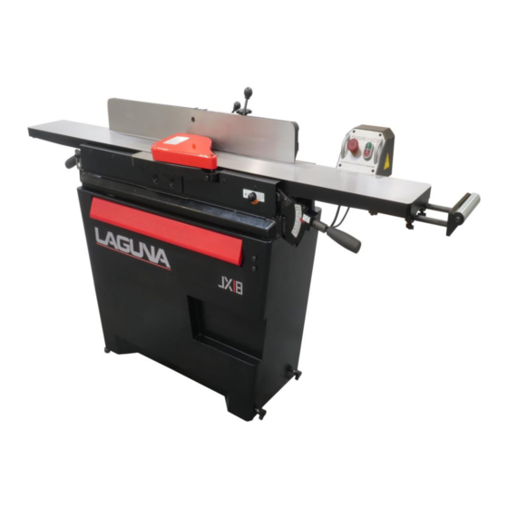
JX|8 Sheartec:II Jointer \ Machine Overview Machine Overview JX|8 Sheartec:II Jointer Figure 1: Main Components A. Emergency Stop (E-STOP); stops all functions of machine, however, power continues to machine. NOTICE! To reset E-STOP, rotate switch clockwise until the button “pops” out. NOTICE! E-STOP bump bar (red) located on front of frame. -
Page 14: Setup
ALL SHIPPING DAMAGE MUST BE NOTED UPON DELIVERY AND SIGNED BY THE OWNER AND THE DELIVERY DRIVER. IF YOU FIND ANY DAMAGED ITEMS IN YOUR PACKAGE, YOU MUST CONTACT LAGUNA TOOLS TO FILE A COMPLAINT. IN ORDER TO RETURN DAMAGED GOODS UNDER THE LIMITED WARRANTY TO LAGUNA TOOLS, INC., YOU MUST HAVE THE ORIGINAL PACKAGING. - Page 15 JX|8 Sheartec:II Jointer \ Setup Placement & Unboxing 6. Allow an area for the storage of blanks, finished products and tools. Unboxing WARNING! THE MACHINE WEIGHS 495 LBS (224KG). ENSURE THAT YOU HAVE ENOUGH PEOPLE TO DO THE JOB SAFELY. ...
-
Page 16: Inventory List
JX|8 Sheartec:II Jointer \ Setup Inventory List Inventory List The following depicts items shipped with your machine. Before assembling, ensure that you have received all parts shown below. Machine parts should arrive sealed in plastic bags. Remove parts from plastic bags before laying them out to inventory them. -
Page 17: Assembling
JX|8 Sheartec:II Jointer \ Setup Assembling Assembling Machine Preparation and Setup: 1. The machine may be supplied with four installed wheels (depending on model), two of which are locking style (infeed side). Lock these two wheels, by turning the thumbscrew clockwise, when the machine is placed and before operation (Fig. - Page 18 JX|8 Sheartec:II Jointer \ Setup Assembling 3. Insert three bolts, with the lock washer and flat washer into each hole of jointer body (Fig. 5). Thread each bolt into the mating nut (factory secured) of the stand. 4. Use a wrench to tighten each bolt. 5.
- Page 19 JX|8 Sheartec:II Jointer \ Setup Assembling Power Supply Circuit Requirements The power source circuit for your machine must be grounded and rated for the amperage given below. Never replace a circuit breaker on an existing circuit with one of higher amperage without consulting a qualified electrician to ensure compliance with wiring codes.
- Page 20 JX|8 Sheartec:II Jointer \ Setup Assembling Calibrating the Thickness Scale FIGURE 9: LOCK PIN FIGURE 8: THICKNESS SCALE 1. Loosen the Infeed Table locking handle by rotating counterclockwise (Fig. 8). 2. Pull and hold the Lock Pin (Fig. 9) while positioning handle to 1/64”. Tighten handle. 3.
- Page 21 JX|8 Sheartec:II Jointer \ Setup Assembling FIGURE 11: Fence Stope & Locks...
-
Page 22: Operation
JX|8 Sheartec:II Jointer \ Operation Operation CAUTION! PLACE THE JOINTER ON A SECURE AND STABLE SURFACE FOR OPERATION. CLAMP OR BOLT THE JOINTER INTO POSITION. 1. Establish the proper depth of cut, (1/8” maximum). However, 1/64” is the recommend cut for the best finish with least chance of kick-back when jointing. - Page 23 JX|8 Sheartec:II Jointer \ Operation Beveling The fence can be adjusted up to 45 degrees angled toward the infeed/outfeed tables (bed) or away from the infeed/outfeed tables (bed) for beveling. There is less chance of stock slippage when the fence is angled down, toward the tables (Fig.
- Page 24 JX|8 Sheartec:II Jointer \ Operation Rabbeting Rabbeting is a grove along the edge of stock. The stock can be on edge or face, depending on the dimensions required for the rabbet. Position fence for width of rabbet cut. This is the distance from the outmost edge of the outermost knife insert to the fence.
-
Page 25: Maintenance
JX|8 Sheartec:II Jointer \ Maintenance Maintenance General Keep your machine clean. At the end of each day, clean the machine. Wood contains moisture, and if sawdust or wood chips are not removed, they will cause rust. In general, we recommend that you only use a Teflon-based lubricant on the jointer. Regular oil attracts dust and dirt. - Page 26 JX|8 Sheartec:II Jointer \ Maintenance Knife rotation/replacement CAUTION! KNIFE INSERTS ARE DANGEROUSLY SHARP. USE EXTREME CAUTION WHEN INSPECTING, REMOVING, OR REPLACING KNIFE INSERTS. WARNING TURN JOINTER OFF AND DISCONNECT POWER BEFORE PERFORMING ANY MAINTENANCE OR ADJUSTMENTS! MAKE SURE ALL KNIFE INSERT SCREWS ARE TIGHTENED SECURELY. LOOSE INSERTS CAN BE PROPELLED AT HIGH SPEED FROM A ROTATING CUTTERHEAD, CAUSING INJURY.
- Page 27 JX|8 Sheartec:II Jointer \ Maintenance Outfeed Table Adjustment: WARNING TURN OFF AND DISCONNECT POWER BEFORE PERFORMING ANY MAINTENANCE OR ADJUSTMENTS! The outfeed table is adjusted at the factory to be level with (or up to max .006” lower than) the Top Dead Center (TDC) of the knife inserts.
- Page 28 JX|8 Sheartec:II Jointer \ Troubleshooting Adjusting Tables Coplanar: WARNING The alignment of the infeed and outfeed tables has been precisely set at the factory. However, misalignment can be incurred from shipping movement. Follow these steps to check and adjust. OVERVIEW These instructions are intended to assist when alignment of the infeed, outfeed or both tables require adjustment.
- Page 29 JX|8 Sheartec:II Jointer \ Wiring Straight Edge Figure 23: Checking Outfeed Table STEP 3: Use a hex wrench (not included) to loosen Screw Lock (S.L) to release outfeed table adjustment lever as shown in FIG. 24. S.L. Outfeed Table Adjustment Lever Figure 24: Screw Lock (S.L) STEP 4: Loosen cap screw on the back (inside) of the outfeed table adjustment lever as shown in FIG.
- Page 30 JX|8 Sheartec:II Jointer \ Troubleshooting Shape FIG. 25: Back View of Outfeed Table Adjustment STEP 5: Place a straight edge in positions shown in FIG. 26 to make sure outfeed table is parallel with the cutterhead. Figure 26: Checking Infeed Table STEP 6: If the outfeed table is not parallel to the cutter head;...
- Page 31 JX|8 Sheartec:II Jointer \ Wiring Figure 27: Straight Edge STEP 3: Place straight edge in positions shown in FIG. 28. Figure 28: Checking Bed Alignment STEP 4: If straight edge lies uniformly flat against both infeed and outfeed tables in all positions; re-install fence, blade guard and rear access panel.
- Page 32 JX|8 Sheartec:II Jointer \ Troubleshooting STEP 2: Remove the plugs and loosen CAP screws to release and remove outfeed table cover as in FIG. 30. Outfeed Table Cover Plug CAP screw Fig. 30: Cover STEP 3: Loosen set screws as shown in FIG. 31. Eccentric Bushings Set Screws (Lock E-...
- Page 33 JX|8 Sheartec:II Jointer \ Wiring STEP 4: Place straight edge to all the positions shown in FIG. 32 and loosen set screw(s) adjust the eccentric bushings, as in FIG. 31, until straight edge slightly touches the cutterhead insert knife (at top-dead-center) at each position.
-
Page 34: Troubleshooting
JX|8 Sheartec:II Jointer \ Troubleshooting Troubleshooting Symptom Possible Cause Possible Solution MACHINE WILL 1. FUSE BLOWN OR CIRCUIT BREAKER TRIPPED 1. REPLACE FUSE OR RESET CIRCUIT BREAKER NOT START CORD DAMAGED HAVE CORD REPLACED NOT CONNECTED TO POWER SOURCE CHECK CONNECTION CONNECTED TO WRONG VOLTAGE CHECK VOLTAGE EMERGENCY STOP BUTTON PRESSED... -
Page 35: Wiring
JX|8 Sheartec:II Jointer \ Wiring Wiring WARNING REVIEW ELECTRICAL SAFETY PRIOR TO ANY WIRING PROCEDURES. MJ8X72E-0130 VOLTAGE 220V PHASE HERTZ 60Hz FULL LOAD AMPERAGE 12 Amp Below are RECOMMENDATIONS to be used for this machine based on the above information. Variables that may affect this are: ... - Page 36 JX|8 Sheartec:II Jointer \ Wiring JX|8 ShearTec: II MJ8X72E-0130...
-
Page 37: Jx8 Sheartec:ii Parts
JX|8 Sheartec:II Jointer \ JX8 Sheartec:II Parts JX8 Sheartec:II Parts Tables & Components... - Page 38 JX|8 Sheartec:II Jointer \ Wiring Cutterhead & Drivetrain...
- Page 39 JX|8 Sheartec:II Jointer \ JX8 Sheartec:II Parts Fence...
- Page 40 JX|8 Sheartec:II Jointer \ JX8 Sheartec:II Parts Stand & Motor...
- Page 41 JX|8 Sheartec:II Jointer \ JX8 Sheartec:II Parts REF NO PART NUMBER DESCRIPTION SPECIFICATION 240080-904 HANDWHEEL 001902-109 SET LOCK SCREW STW-12 010003-000 RETAINING RING 381336-901 LEAD SCREW 006001-087 FLAT WASHER 12x25x1.5 250372-615 FENCE TILT KNOB 360038-901 HANDLE ROD 003103-102 CAP SCREW ¼-20 x 1/2”...
- Page 42 JX|8 Sheartec:II Jointer \ JX8 Sheartec:II Parts REF NO PART NUMBER DESCRIPTION SPECIFICATION 000701-103 FLAT HEAD HEX SCREW M5-0.8x12 171841-902 LEAD SCREW 006001-034 FLAT WASHER 6.7x16x2.0 051355-196 FENCE BRACKET WW-19 (19.05x26) 006722-100 WAVE WASHER 012003-008 5X5X22 381409-902 PULLEY 7 SLOTS 001902-102 SET LOCK SCREW M6X1.0X8...
- Page 43 JX|8 Sheartec:II Jointer \ JX8 Sheartec:II Parts REF NO PART NUMBER DESCRIPTION SPECIFICATION 361370-902 HANDLE SHAFT BOLT 002602-101 CAP LOCK SCREW M6X1.0X12 361327-902 HANDLE SHAFT BOLT 290028-901 SHOULDER SCREW 174603-902 FIXING PLATE 009103-100 LOCK NUT 1/4”-20NC (11BX8H) 008004-100 HEX NUT M5X0.8(8BX4H) 280082-000 TENSION SPRING...
- Page 44 COVER 000403-104 FLAT HEAD PHILLIPS SCREW M6X1.0X20 230049-000 FOOT 925094-001 EXTENSION ROLLER ASSEMBLY 8" 950807-001 CONTROL BOX ASSEMBLY 208-240V 174936-000 CONTROL BOX LAGUNA 575288-000 SWITCH PLATE LAGUNA 491153-000 EMERGENCY STOP SWITCH NPB22-H01R 491223-000 POWER SWITCH M22DP-SF11WB 491140-000 CONTACTOR SF20C2B(208-240V) 300117-909...
- Page 45 JX|8 Sheartec:II Jointer \ JX8 Sheartec:II Parts REF NO PART NUMBER DESCRIPTION SPECIFICATION 174695-902 HOOK 006001-001 FLAT WASHER 4.3X10X1.0 000302-101 PAN HEAD SCREW M4X0.7X6 006502-100 WASHER, INT/TOOTH 5.3X10 (BW-5) 000102-103 CAP SCREW M5X0.8X10 130405-903 BUSHING BLOCK 000103-103 CAP SCREW M6X1.0X12 250705-000 WING SCREW M6X1.0...
- Page 46 JX|8 Sheartec:II Jointer \ Warranty...
-
Page 47: Warranty
Minnesota: 5250 West 74th St, Edina, MN 55439, U.S.A Phone: +1-949-474-1200 DAKE CORPORATION 724 Robbins Road, Grand Haven, MI 49417, United States +1-800-937-3253 LAGUNA EUROPE Walker Rd, Bardon Hill, Coalville LE67 1TU, United Kingdom. Phone: +44-1530-516921 © 2021 Laguna Tools 092122...
Need help?
Do you have a question about the Sheartec II JX 8 and is the answer not in the manual?
Questions and answers