Table of Contents
Advertisement
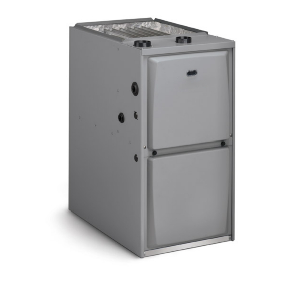
SERVICE MANUAL
96G2UHV Gas Furnace
This is a safety alert symbol and should never be ignored. When you see this symbol on labels or in manuals, be alert to
the potential for personal injury or death.
Improper installation, adjustment, alteration, service
or maintenance can cause property damage, personal
injury or loss of life. Installation and service must be
performed by a licensed professional HVAC installer (or
equivalent), service agency or the gas supplier.
As with any mechanical equipment, contact with sharp
sheet metal edges can result in personal injury. Take
care while handling this equipment and wear gloves
and protective clothing.
508183-01
WARNING
CAUTION
Table of Contents
Technical Specifications - 96G2UHV ...........................2
Parts Arrangement.......................................................5
Unit Components .........................................................6
Heating Components .................................................12
Placement and Installation ........................................17
Joint Cementing Procedure .......................................18
Venting Practices .......................................................19
Vent Piping Guidelines ..............................................23
Condensate Piping ....................................................37
Start-Up .....................................................................42
Heating System Service Checks ...............................43
Proper Ground and Voltage .......................................46
Typical Operating Characteristics ..............................47
Maintenance ..............................................................48
Wiring and Sequence of Operation ...........................51
Electric shock hazard.
Can cause injury or death. Before attempting
to perform any service or maintenance,
turn the electrical power to unit OFF at
disconnect switch(es). Unit may have
multiple power supplies.
*P508183-01*
Issue 2114
WARNING
(P) 508183-01
Page 1 of 52
Advertisement
Table of Contents

Related Manuals for Allied 96G2UH045BV12


Summary of Contents for Allied 96G2UH045BV12
-
Page 1: Table Of Contents
SERVICE MANUAL 96G2UHV Gas Furnace This is a safety alert symbol and should never be ignored. When you see this symbol on labels or in manuals, be alert to the potential for personal injury or death. Table of Contents Technical Specifications - 96G2UHV ......2 Parts Arrangement............5 Unit Components ............6 Heating Components ..........12... -
Page 2: Technical Specifications - 96G2Uhv
Inlet (ICS) Breaker F.L.A. (V.A.) Weight Input Output* Input Output* Capacity (in.) Phase or Fuse (lbs.) (Btuh) (Btuh) (Btuh) (Btuh) 96G2UH045BV12 29,000 28,000 44,000 42,000 96.0 120-60-1 96G2UH070BV12 43,000 41,000 66,000 62,000 96.0 120-60-1 96G2UH090CV12 57,000 55,000 88,000 84,000 96.0... - Page 3 "B" "A" "D" "C" “B” "A" (°F) 1005 1075 1210 1370 35-65 High 1120 1255 Norm Stage Fire 1020 1135 96G2UH045BV12 10x9 20-50 Norm Stage Fire 1060 1130 1255 1060 1215 1365 50-80 High 1140 1130 1265 Norm Stage Fire...
- Page 4 ACCESSORY LIST Catalog Number Description External Filter Rack Kits 1.841018 1 pack (16 x 25) 1.841039 10 pack (16 x 25) Natural to LP Kits 11K48 2-Stage – 90 11K47 High Altitude 2-Stage (>4500') Return Air Base 68W62 17.5" B Width 68W63 21.0"...
-
Page 5: Parts Arrangement
Parts Arrangement Figure 1. 508183-01 Issue 2114 Page 5 of 52... -
Page 6: Unit Components
Unit Components WARNING 96G2UHV unit components are shown in Figure 1. The gas Shock hazard. valve, combustion air inducer and burners can be accessed Disconnect power before servicing. Integrated control by removing the access panel. Electrical components are is not field repairable. If control is inoperable, simply in the control box (Figure 2) found in the blower section. - Page 7 CFM LED Pin # Function An amber LED is provided on the control board to display Gas Valve Second Stage CFM. To determine what CFM the motor is delivering Second Stage Prove Switch at any time, count the number of times the amber LED flashes.
- Page 8 Heat Stage Jumper (single stage shown) Air Flow Heat Jumper Taps Cool Taps TERMINAL DESIGNATIONS HUM -Humidifier (120VAC) Line - Input (120VAC) XFMR - Transformer (120VAC) EAC - Indoor Air Accessory (120VAC) Cool - Cool Speed (120VAC) Park 1 - Dead terminal for alternate speed tap Park 2 - Dead terminal for alternate speed tap Figure 3.
- Page 9 Indoor Blower Motor MOTOR CONTROLLER Figure 5. GenTeq Blower Motor B3 Power Choke STATOR Blower Motor (WINDINGS) (4 and 5 Ton Only) (B3) BEARING Figure 4. OUTPUT SHAFT ROTOR WARNING During blower operation, the ECM motor emits Figure 6. Blower Motor Components energy that may interfere with pacemaker operation.
- Page 10 Initial Power Up POWER CONTROL When line voltage is applied to B3, there will be a large CONNECTOR J48 CONNECTOR J49 inrush of power lasting less than 1/4 second. This inrush PIN 1 C1 PIN 2 W / W1 charges a bank of DC filter capacitors inside the controller. PIN 3 C2 If the disconnect switch is bounced when the disconnect is PIN 4 - Delay...
- Page 11 Motor speed is determined by the size of the electrical pulse sent to the motor windings. The longer the pulse, the faster the motor. OUTPUT FROM CONTROLLER TO MOTOR WINDINGS WINDINGS TURNED OFF WINDINGS TURNED ON ON PULSE OFF PULSE The frequency of the pulses to the windings is 20KHz.
-
Page 12: Heating Components
The pressure switch measures the pressure LPG change over kits are available from Allied Air. Kits differential across the combustion air inducer orifice or include burner orifices and a gas valve. - Page 13 Burner Assembly Intake Air Top Cap Sensor Rollout Switch Rollout Switch Ignitor Manifold And Gas Orifices Burner Box Cover Two-Stage Gas Valve Figure 9. Heating Components 508183-01 Issue 2114 Page 13 of 52...
- Page 14 Test 1 Check ignitor circuit for correct resistance. Remove 4-pin plug from control. Check ohms reading across terminals 1 and 5. Reading should be between 39 and 70 ohms. If value is correct, this is the only test needed. If the reading on the meter is not correct, (0 or infinity) then a second test is needed.
- Page 15 Combustion Air Inducer Pressure Switch (S18) Pressure Switch Check 96G2UHV series units are equipped with a dual combustion To check pressure switch differential, refer to Figure 12 air pressure switch (first and second stage) located on the and use the provided fittings and tubing to follow the steps combustion air inducer orifice bracket.
- Page 16 Black Tubing 2” long Square (positive +) Tubing Red and Black or Red Tubing (negative -) 10” Long Square Tubing Measuring Device Figure 12. Pressure Switch Check Page 16 of 52 Issue 2114 508183-01...
-
Page 17: Placement And Installation
Canadian Applications Only - Pipe, fittings, primer and Placement and Installation solvent cement used to vent (exhaust) this appliance must be certified to ULC S636 and supplied by a single All pipe, fittings, primer and solvent cement must conform manufacturer as part of an approved vent (exhaust) with American National Standard Institute and the American system. -
Page 18: Joint Cementing Procedure
STANDARD CONCENTRIC Outdoor Outdoor Exhaust Flush 1-1/2” 2” 3” Exhaust VENT PIPE Accelerator Mount Concentric Concentric Concentric Accelerator 96G2UHV DIA. (Dia. X Length) (Dia. X Length) (in.) 71M80 69M29 60L46 1-1/2” X 12” 2” X 12” 51W11 * or 44W93+ +44W92++ +44W92++ 1-1/2... -
Page 19: Venting Practices
Removal of the Furnace from Common Vent are wet with cement, forcefully insert end of pipe into socket until it bottoms out. Turn PVC pipe 1/4 turn during assembly (but not after pipe is fully inserted) to WARNING distribute cement evenly. DO NOT turn ABS or cellular core pipe. - Page 20 Exhaust Piping (Figure 15 and Figure 16) Close all building doors and windows and all doors between the space in which the appliances remaining Route piping to outside of structure. Continue with connected to the common venting system are located installation following instructions given in piping termination and other spaces of the building.
- Page 21 TYPICAL EXHAUST PIPE CONNECTIONS IN HORIZONTAL DIRECT OR NON-DIRECT VENT APPLICATIONS (RIGHT-HAND DISCHARGE SHOWN) NOTE: 1-1/2” Vent Pipe Diameter Allowed Only on 045/070 Units 12” max. 2” 1-1/2” 2” 3” TRANSITION TRANSITION 2” 2” 2” 2” *2” *2” 2” EXHAUST EXHAUST EXHAUST 45°...
- Page 22 TYPICAL INTAKE PIPE CONNECTIONS IN UPFLOW DIRECT OR NON-DIRECT VENT APPLICATIONS 2” 3” Pipe size determined in Table 5 TRANSITION INTAKE *2” 2” 2” 2” 2” * When transitioning up in pipe size, use the shortest length of 2” PVC pipe possible. NOTE: Exhaust pipe and intake pipe must be the same diameter.
-
Page 23: Vent Piping Guidelines
Vent Piping Guidelines CAUTION NOTE: Allied Air has approved the use of DuraVent ® If this unit is being installed in an application with Centrotherm manufactured vent pipe and terminations as combustion air coming in from a space serviced by an an option to PVC. - Page 24 Use the following steps to correctly size vent pipe diameter. Exhaust Pipe 12” Min. 12” Max. Horizontal 045, 070, Gas Furnace Furnace capacity? 090, 110 or 135 btuh NOTE - Standard or ward unit. A minimum of 1/4” (6mm) drop for each 12” (305mm) Which termination? Concentric? of horizontal run is mandatory for drainage.
- Page 25 Maximum Allowable Intake or Exhaust Vent Length in Feet Standard Termination at Elevation 0 - 4500 ft Number 1-1/2" Pipe 2" Pipe 2-1/2" Pipe 3" Pipe of 90° Model Model Model Model Elbows Used Standard Termination Elevation 4500 - 10,000 ft 1-1/2"...
- Page 26 Maximum Allowable Intake or Exhaust Vent Length in Feet Concentric Termination at Elevation 0 - 4,500 ft Number 1-1/2" Pipe 2" Pipe 2-1/2" Pipe 3" Pipe of 90° Model Model Model Model Elbows Used Concentric Termination Elevation 4,501 - 10,000 ft 1-1/2"...
- Page 27 Maximum Allowable Exhaust Vent Lengths with Furnace Installed in a Closet or Basement Using Ventilated Attic or Crawl Space for Intake Air in Feet Standard Termination at Elevation 0 - 4500 ft Number 1-1/2" Pipe 2" Pipe 2-1/2" Pipe 3" Pipe of 90°...
- Page 28 General Guidelines for Vent Terminations In Non-Direct Vent applications, combustion air is taken IMPORTANT from indoors or ventilated attic or crawlspace and the flue gases are discharged to the outdoors. The 96G2UHV Do not use screens or perforated metal in exhaust is then classified as a non-direct vent, Category IV gas terminations.
- Page 29 Maximum Allowable Exhaust Vent Pipe Length (in ft.) without Insulation in Unconditioned Space for Winter Design Temperatures Winter Design Unit Input Size Temperatures ºF Vent Pipe (ºC) Diameter 1-1/2 in. 32 to 21 2 in. (0 to -6) 2-1/2 in. 3 in.
- Page 30 ‡ Permitted only if veranda, porch, deck or balcony is fully open on a minimum of two sides beneath the floor. Allied Air recommends avoiding this location if possible. Figure 24. Vent Termination Clearances Direct Vent Installations...
- Page 31 Details of Intake and Exhaust Piping Intake and exhaust pipes should be placed as close together as possible at termination end (refer to Terminations for Direct Vent Installations illustrations). Maximum separation is 3” (76MM) NOTE: In Direct Vent installations, combustion air is taken on roof terminations and 6”...
- Page 32 On field-supplied terminations, a minimum distance STRAIGHT-CUT OR between the end of the exhaust pipe and the end of ANGLE-CUT IN DIRECTION OF ROOF SLOPE * the intake pipe without a termination elbow is 8” and a minimum distance of 6” with a termination elbow. See 3”...
- Page 33 ‡ Permitted only if veranda, porch, deck or balcony is fully open on a minimum of two sides beneath the floor. Allied Air recommends avoiding this location if possible. Figure 33. Vent Termination Clearances...
- Page 34 Details of Exhaust Piping Terminations for Non- STRAIGHT-CUT OR * SIZE TERMINATION PIPE PER EXHAUST Direct Vent Applications ANGLE-CUT IN DIRECTION PIPE TERMINATION SIZE REDUCTION TABLE OF ROOF SLOPE * Exhaust pipes may be routed either horizontally through an outside wall or vertically through the roof. In attic or closet installations, vertical termination through the EXHAUST VENT Minimum 12”...
- Page 35 Exhaust through Crawl Space Vent Option All 33” condensing gas furnaces (92%+) are now approved Exhaust from to be vented down through a crawl space. Ensure a vent Furnace pipe drain kit, 51W18 (USA) or 15Z70 (Canada), is used as To Termination directed through the floor joists and into the crawl space.
- Page 36 FIELD FABRICATED WALL TERMINATION NOTE − FIELD−PROVIDED REDUCER MAY BE 2” (51mm) 3” (76mm) REQUIRED TO ADAPT Vent Pipe Vent Pipe LARGER VENT PIPE SIZE TO TERMINATION A− Minimum clearance above grade or average 12” (305 mm) 12” (305 mm) snow accumulation B−...
-
Page 37: Condensate Piping
Determine which side condensate piping will exit the Condensate Piping unit, location of trap, field-provided fittings and length of PVC pipe required to reach available drain. This unit is designed for either right- or left-side exit of Use a large flat head screw driver or a 1/2” drive condensate piping in upflow applications. - Page 38 line should be routed within the conditioned space to avoid freezing of condensate and blockage of drain line. If this is not possible, a heat cable kit may be used on the condensate trap and line. Heating cable kit is available in various lengths;...
- Page 39 Evaporator drain From Evaporator Coil line required Field Provided Vent 1” min. 2” max. above (Trap at coil is optional) condensate drain. Field-Provided Vent (1” min. to 2” Max.above condensate drain connection) Furnace Condensate Condensate Drain Condensate Drain Connection Optional Overflow Switch Figure 46.
- Page 40 Optional Condensate Drain Connection Adapter 3/4 inch slip X 3/4 inch mpt (not furnished) 90° Street Elbow 3/4 inch PVC (not furnished) Adapter 3/4 inch slip X 3/4 inch mpt (not furnished) Condensate Drain Connection In Unit 1 (25 mm) Min. Vent 2 (50 mm) Max.
- Page 41 Optional Condensate Drain Connection Adapter 1/2 inch slip X 1/2 inch mpt (Not Furnished) 90° Street Elbow 1/2 inch PVC (Not Furnished) Adapter 1/2 inch slip X 1/2 inch mpt (Not Furnished) Condensate Drain Connection In Unit 1 (25 mm) Min. Vent 2 (50 mm) Max.
-
Page 42: Start-Up
Placing the Furnace into Operation Start-Up 96G2UHV units are equipped with an ignition system. Do NOT attempt to manually light burners on this furnace. Preliminary and Seasonal Checks Each time the thermostat calls for heat, the burners will Inspect electrical wiring, both field and factory installed automatically light The ignitor does not get hot when there for loose connections. -
Page 43: Heating System Service Checks
Gas Piping This furnace is equipped with an ignition device which automatically lights the burners. Do not try to light the burners by hand. CAUTION Remove the upper access panel. If a flexible gas connector is required or allowed by Move gas valve switch to OFF. - Page 44 When checking piping connections for gas leaks, use Shut unit off and remove manometer as soon as an preferred means. Kitchen detergents can cause harmful accurate reading has been obtained. corrosion on various metals used in gas piping. Use of a Start unit and perform leak check.
- Page 45 Proper Combustion High Altitude Furnace should operate minimum 15 minutes with correct The manifold pressure, gas orifice and pressure switch manifold pressure and gas flow rate before checking may require adjustment or replacement to ensure proper combustion. Take combustion sample beyond the flue operation at higher altitudes.
-
Page 46: Proper Ground And Voltage
Proper Ground and Voltage In addition, measure the AC voltage from Line Hot A poorly grounded furnace can contribute to premature ignitor failure. Use the following procedure to check for to Line Neutral (spade terminals) on the integrated control. See Figure 52. This voltage should be in the ground and voltage to the integrated control. -
Page 47: Typical Operating Characteristics
External Static Pressure Typical Operating Characteristics 1. Tap locations shown in Figure 54. Punch a 1/4” diameter hole in supply and return air Blower Operation and Adjustment plenums. Insert manometer hose flush with inside Blower operation is dependent on thermostat control edge of hole or insulation. -
Page 48: Maintenance
Maintenance Furnace Cabinet Width Minimum Filter Size 17-1/2” 16 x 25 x 1 (1) 21” WARNING Table 18. ELECTRICAL SHOCK, FIRE, OR EXPLOSION HAZARD. Exhaust and Air Intake Pipes Failure to follow safety warnings exactly could result in Check the exhaust and air intake pipes and all connections dangerous operation, serious injury, death or property for tightness and to make sure there is no blockage. - Page 49 Reinstall screens, reconnect hoses and turn on power 13. Mark and remove wires from pressure switch assembly. to unit. Remove the assembly. Keep tubing attached to pressure switches. 14. Disconnect the plug from the combustion air inducer. Remove two screws which secure combustion air inducer to collector box.
- Page 50 33. Carefully connect combustion air pressure switch Mark and disconnect sensor wire from the sensor. tubing from pressure switches to proper ports on cold Disconnect wires from flame rollout switches. end header collector box. Disconnect combustion air intake pipe. It may be 34.
-
Page 51: Wiring And Sequence Of Operation
Wiring and Sequence of Operation NOTES: PRESS AND RELEASE FAULT CODE HISTORY BUTTON TO DISPLAY FAULT CODES. TO ERASE CODES, PRESS AND HOLD BUTTON IN FOR MORE THAN 5 SECONDS IF ANY OF THE ORIGINAL WIRE AS SUPPLIED WITH THE FURNACE MUST BE REPLACED, IT MUST BE REPLACED WITH WIRING MATERIAL HAVING A TEMP. - Page 52 Sequence of Operation Cooling The unit is set up at the factory for single stage cooling. On a call for heat from the room thermostat, the control For two stage cooling operation, clip the jumper wire board performs a 1 second self check. Upon confirmation located between the Y to Y2 terminals on the integrated that the pressure switch contacts are in an open position, ignition/blower control board.
Need help?
Do you have a question about the 96G2UH045BV12 and is the answer not in the manual?
Questions and answers