Sign In
Upload
Manuals
Brands
Allied Manuals
Furnace
96G2UH110CV20
User Manuals: Allied 96G2UH110CV20 Gas Furnace
Manuals and User Guides for Allied 96G2UH110CV20 Gas Furnace. We have
2
Allied 96G2UH110CV20 Gas Furnace manuals available for free PDF download: Installation Instructions Manual, Service Manual
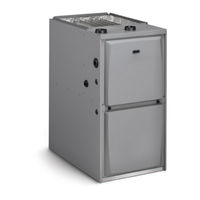
Allied 96G2UH110CV20 Installation Instructions Manual (59 pages)
Warm Air Gas Furnace Upflow/Horizontal Left Air Discharge Direct Vent & Non-Direct Vent
Brand:
Allied
| Category:
Furnace
| Size: 6 MB
Table of Contents
Table of Contents
1
Unit Dimensions
2
Product View
3
Parts Arrangement
3
Gas Furnace
4
Shipping and Packing List
4
Safety Information
4
Building Codes
5
Installed Locations
5
Installed in Combination with a Cooling Coil
5
Use of Furnace as a Construction Heater
6
General
6
Combustion, Dilution & Ventilation Air
7
Unconfined Space
7
Confined Space
7
Air from Outside
8
Air from Inside
8
Shipping Bolt Removal
9
Setting Equipment
10
Upflow Applications
10
Installation Clearances
10
Installation
10
Return Air Guidelines
11
Optional Return Air Base
11
Removing the Bottom Panel
12
Horizontal Applications
12
Suspended Installation of Horizontal Unit
13
Platform Installation of Horizontal Unit
13
Return Air - Horizontal Applications
13
Filters
13
Pipe & Fittings Specifications
14
Supply Air Plenum
14
Return Air Plenum
14
Duct System
14
Joint Cementing Procedure
15
Venting Practices
15
Exhaust Piping
16
Removal of the Furnace from Common Vent
16
Vent Piping Guidelines
17
Exhaust Pipe Horizontal Application
18
Minimum Vent Pipe Lengths
18
Maximum Allowable Intake or Exhaust Vent Length in Feet
19
Maximum Allowable Exhaust Vent Lengths
21
Typical Exhaust Pipe Connections
22
Intake Piping
23
Typical Intake Pipe Connections
23
Equipment in Confined Space
24
Typical Air Intake Pipe Connections
24
General Guidelines for Vent Terminations
25
Insulating Exhaust Pipe in an Unconditioned Space
26
Vent Termination Clearances for Non-Direct Vent Installations
27
Vent Termination Clearances for Direct Vent Installations
28
Intake/Exhaust Piping Terminations for Direct Vent Installations
29
Direct Vent Roof Termination Kit
29
Exiting Exhaust and Intake Vent
29
Exhaust Pipe Termination Size Reduction
29
Direct Vent Concentric Rooftop Termination
30
Flush-Mount Side Wall Termination
30
Optional Vent Termination for Multiple Unit Installation
30
Direct Vent Application Using Existing Chimney
30
Field Fabricated Wall Termination
31
Alternate Terminations
31
Exhaust Piping Terminations for Non-Direct Vent Applications
32
Exhaust through Crawl Space Vent Option
33
Crawl Space Vent Pipe Drain Trap Assembled Incorrectly
33
Upflow or Downflow Furnace with Exhaust through Crawl Space
33
Condensate Trap and Plug Locations
34
Condensate Piping
34
Condensate Trap Locations
35
Unit with Evaporator Coil Using a Separate Drain
35
Evaporator Coil Using a Common Drain
35
Trap / Drain Assembly Using 1/2” PVC or 3/4” PVC
36
Condensate Trap with Optional Overflow Switch
37
Gas Piping
37
Horizontal Applications Possible Gas Piping Configurations
38
Upflow Applications Possible Gas Piping Configurations
38
Gas Pipe Capacity
39
Electrostatic Discharge
40
Interior Make-Up Box Installation
40
Electrical
40
Indoor Blower Speeds
41
Generator Use - Voltage Requirements
41
Electrical Wiring
41
Thermostat
41
Electronic Air Cleaner
42
Variable Speed Features
42
Passive and Active Dehumidification
42
Circulating Airflow Adjustments
42
Heat Pump
43
Two Stage Cooling
43
Single Stage Cooling
43
Sequence of Operation
43
Indoor Blower Operation Diagrams
44
Emergency Replacement Motor Operation
45
Control Diagnostics
45
Fault Code History Button
45
Cfm Led
45
Typical Field Wiring Diagram
46
Typical Wiring Diagram
47
Blower Performance
48
Allowable Heating Speeds
51
Placing the Furnace into Operation
52
Gas Valve Operation
52
Unit Start-Up
52
Gas Pressure Adjustment
53
Failure to Operate
53
Heating Sequence of Operation
53
Turning off Gas to Unit
53
Manifold Pressure Measurement
54
Proper Combustion
54
High Altitude Information
54
Electronic Ignition
54
Other Unit Adjustments
54
Exhaust and Air Intake Pipes
55
Winterizing and Condensate Trap Care
55
Cleaning Heat Exchanger
55
Service
55
Cleaning the Burner Assembly
56
Planned Service
57
Repair Parts List
57
Advertisement
Allied 96G2UH110CV20 Service Manual (52 pages)
Brand:
Allied
| Category:
Furnace
| Size: 4 MB
Table of Contents
Table of Contents
1
Technical Specifications - 96G2UHV
2
Parts Arrangement
5
Unit Components
6
Heating Components
12
Placement and Installation
17
Joint Cementing Procedure
18
Venting Practices
19
Vent Piping Guidelines
23
Condensate Piping
37
Start-Up
42
Heating System Service Checks
43
Proper Ground and Voltage
46
Typical Operating Characteristics
47
Maintenance
48
Wiring and Sequence of Operation
51
Advertisement
Related Products
Allied 96G2UHV
Allied 96G2UH045BV12
Allied 96G2UH070BV12
Allied 96G2UH090CV12
Allied 96G2UH090CV20
Allied 96G2UH135DV20
Allied 96G2DFV
Allied 96G2DF070BV16
Allied 96G2DF110CV20
Allied 96G2DF090CV20
Allied Categories
Furnace
Heat Pump
Construction Equipment
Air Conditioner
Air Handlers
More Allied Manuals
Login
Sign In
OR
Sign in with Facebook
Sign in with Google
Upload manual
Upload from disk
Upload from URL