Table of Contents
Advertisement
Advertisement
Table of Contents

Related Manuals for Dantherm HRC 3


Summary of Contents for Dantherm HRC 3
- Page 1 HRC 3 User manual Rev. 1.1...
- Page 2 Der tages forbehold for trykfejl og ændringer Dantherm can accept no responsibility for possible errors and changes Irrtümer und Änderungen vorbehalten Dantherm n’assume aucune responsabilité pour erreurs et modifications éventuelles...
-
Page 3: Table Of Contents
General description ....................4 Installation ......................5 Display information ..................... 6 User menu ......................7 Operating information - without accessories............12 Operation information, with accessories ............. 14 Installer menu / installer mode ................16 Appendix ......................21 Contact Dantherm....................22... -
Page 4: General Description
General description Introduction This remote control is designed for the particular and considerate house owner, who is especially keen to provide a pleasant indoor climate in his house and to its occupants. The remote control communicates wireless with the control panel of the ventilation unit up to a range of 30 meter through walls and lightweight floors. -
Page 5: Installation
Installation Pairing The remote control has to be paired with the ventilation unit before use. Follow the pro- cedure below to pair the wireless remote control with the ventilation unit: Step Action Disconnect the power to the ventilation unit Open the battery lid on the remote control and insert the batteries (2 x AAA) which are included with the remote control. -
Page 6: Display Information
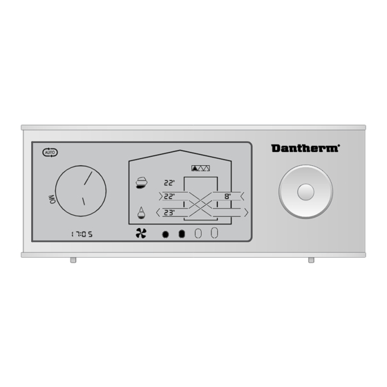
Display information Display OPERATING PROGRAMS OPERATING INFORMATION overview FAN SPEED NAVIGATION BUTTON INFO LINE HOUR/DAY Display description The following table describes the symbols and buttons on the remote control. The remote control has an energy saving function which switches off the display be- tween 23:00 and 7:00. -
Page 7: User Menu
User menu User menus In the USER MENU you will find the following operating programs and operating info Read after Set fan speed Set week pro- Away mode Night mode heater Read filter re- Set auto no Set time (1-4) gram (1-11) on / off on / off... - Page 8 User menu, continued Operation programs On the remote control you can choose among different operation modes allowing you to control the ventilation in accordance with different demands. Symbol Description Demand-control In AUTO mode the unit adjusts automatically between fan step 1 - 3, so that the air change matches the actual demand in the house.
- Page 9 User menu, continued Symbol Description Night mode In Night mode the unit runs at fan step 1, and this mode functions to- gether with Auto, Manual or Week program mode. Start and end time for night mode are set in the following way: Step Action When night mode is activated (symbol flashes) press DOWN and...
- Page 10 User menu, continued Afterheating settings Step Action Activate the menu line by pressing CENTER Press RIGHT to navigate to afterheater icon. The afterheater icon flashes slowly (30/min). Simultaneously T2, T3 and T5 continue to show the real temperatures in the unit. Press CENTER to navigate to the AFTERHEATER menu.
- Page 11 User menu, continued Fire-place Fireplace function function The fireplace function is designed to create overpressure in the house, so that the fireplace can be lit without problems. The overpressure is created by reducing the extraction and maintaining the supply at fan step 3. The function is activated/deactivated by pressing UP for 5 seconds, then FP07 is shown in the INFO LINE = fireplace mode for 7 min.
-
Page 12: Operating Information - Without Accessories
Operating information - without accessories. Operating infor- The display shows various operating information according to the actual operation mation mode. Two different screens are shown, depending on whether the unit is running in HEAT RECOVERY MODE or BYPASS-COOLING mode. Heat recovery/ by- (T5) pass-cooling (T3) - Page 13 Operating information - without accessories., continued Info-line Information about alarms, various settings and battery level are shown in the INFO- (Under the clock) LINE. Symbol Description If the ALARM icon is displayed, there is a failure on the unit, and the defect component is flashed.
-
Page 14: Operation Information, With Accessories
Operation information, with accessories Operating infor- Various operating information is shown on the display depending on the actual opera- mation tion mode of the unit and the accessories which are in operation. Two different screens are shown on the display depending on whether the unit is in heat RECOVERY mode or BYPASS-COOLING mode. - Page 15 Operation information, with accessories, continued In AUTO mode the unit is controlled by the VOC, CO and RH% at the same time. VOC/CO control: If a VOC (accessory) or CO -sensor (accessory connected via HAC) is connected and the unit is set to AUTO mode the airflow is con- trolled by the pollution concentration measured by the sensor.
-
Page 16: Installer Menu / Installer Mode
3 is maintained. Warning: Dantherm Air Handling A/S disclaims any responsibility if the unit is installed in a way that has a negative influence either on the heat consumption in the house, or the indoor climate or if the unit is installed in such a way that the building, the building structure and the furniture are damaged. - Page 17 Installer menu / installer mode, continued RH% Set point In AUTO menu, the RH% setpoint for demand-control can be set. The RH% setpoint be- (accessory longs to the selected AUTO program No. required) Warning: If the RH% setpoint is set too low it may result in inconvenience for the occupants of the house and materials in the house may dry up.
- Page 18 Installer menu / installer mode, continued Preheater If preheating is installed (accessory) connected, the icon will appear on the display when the heater is on. Furthermore the preheater can be enabled/disabled in the installer menu. Ventilation unit icon Enable/disable (preheater icon) °...
- Page 19 Installer menu / installer mode, continued BYPASS-COOLING In BYPASS-COOLING operation the air channels are parallel through the unit (no heat setpoints recovery). If pre-/aftercooling is connected, the icons for these components will be shown when they are in operation only. In the installer menu you can see/change the setpoints for BYPASS-COOLING on the lo- cations shown below.
- Page 20 Installer menu / installer mode, continued BYPASS-COOLING If Pre-/aftercooling coils are installed they are controlled by the same setpoints and strategy control strategy as the built-in BYPASS-COOLING function. I.e. Pre-/aftercooling and bypass are always switched on at the same time. If Aftercooling is installed it will be used together with “cooling recovery mode”...
-
Page 21: Appendix
Appendix Alarm codes Code Alarm / Errors Exhaust air fan Supply air fan By-pass damper Extract air temperature sensor (T1) Supply air temperature sensor (T2) Extract air temperature sensor (T3) Exhaust air temperature sensor (T4) Room air temperature sensor (T5) Humidity sensor (RH), placed in the extract air duct of the unit. -
Page 22: Contact Dantherm
P1 - Week program Monday - Friday Step Weekend Step P2 - Week program Monday - Friday Step Weekend Step P3 - Week program Monday - Friday Step Weekend Step P4 - Week program Monday - Friday Step Weekend Step... - Page 23 P5 - Week program Monday - Friday Step Weekend Step P6 - Week program Monday - Friday Step Weekend Step P7 - Week program Monday - Friday Step Weekend Step P8 - Week program Monday - Friday Step Weekend Step...
- Page 24 P9 - Week program Monday - Friday Step Weekend Step P10 - Week program Monday - Friday Step Weekend Step P11 - Week program Monday - Friday Step Set week program 11 in PC-tool. Fan speed can be set according Demand (accessory) or fixed Weekend Step Set week program 11 in PC-tool.
- Page 27 +(0) 121 133 70 infodk@dantherm.com dantherm.no@dantherm.com infose@dantherm.com www.dantherm.com www.dantherm.no www.dantherm.se Dantherm Air Handling (Suzhou) Ltd. Dantherm Limited Dantherm Air Handling Inc. Bldg#9, No.855 Zhu Jiang Rd., 12 Windmill Business Park 110 Corporate Drive, Suite K Suzhou New District, Jiangsu Windmill Road, Clevedon...
- Page 28 Dantherm Air Handling A/S Marienlystvej 65 7800 Skive Denmark www.dantherm.com service@dantherm.com...
Need help?
Do you have a question about the HRC 3 and is the answer not in the manual?
Questions and answers