Advertisement
Advertisement
Table of Contents

Subscribe to Our Youtube Channel
Related Manuals for Dantherm HRC 2


Summary of Contents for Dantherm HRC 2
-
Page 1: Table Of Content Table Of Content
HRC 2 User manual Rev. 1.1... - Page 2 Der tages forbehold for trykfejl og ændringer Dantherm can accept no responsibility for possible errors and changes Irrtümer und Änderungen vorbehalten Dantherm n’assume aucune responsabilité pour erreurs et modifications éventuelles...
-
Page 3: Table Of Contents
Table of content Table of content Table of content ....................1 General description ....................4 Installation ......................5 Display information ..................... 6 User menu ......................7 Operating information, without accessories............12 Operation information, with accessories ............. 14 Installer menu / installer mode ................16 Appendix ...................... -
Page 4: General Description
General description Introduction This remote control is designed for the particular and considerate houseowner, who is especially keen to provide a pleasant indoor climate in his house and to its occupants. The remote control communicates wireless with the control panel of the ventilation unit up to a range of 30 meter through walls and lightweight floors. -
Page 5: Installation
Installation Pairing The remote control has to be paired with the ventilation unit before use. Follow the pro- cedure below to pair the wireless remote control with the ventilation unit: (communica- tion is between the control panel (HCP4) and the remote control (HRC2)) Step Action Disconnect the power to the ventilation unit... -
Page 6: Display Information
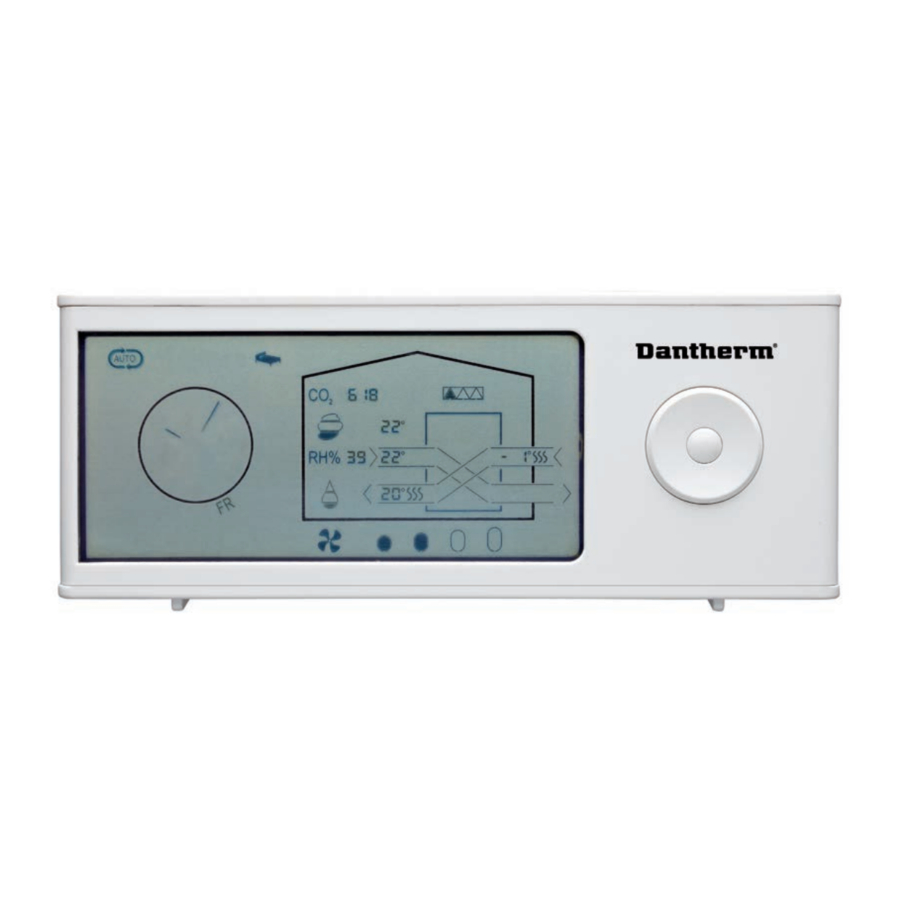
Display information Display OPERATING PROGRAMS OPERATING INFORMATION overview FAN SPEED NAVIGATION BUTTON INFO LINE HOUR/DAY Display description The following table describes the symbols and buttons on the remote control. The remote control has an energy saving function which switches off the display be- tween 23:00 and 7:00. -
Page 7: User Menu
User menu User menus In the USER MENU you will find the following operating programs and operating info: Navigation button Button Function Activates the user menu, a menu point or confirms settings by pressing the CENTER button. Navigates between menu points by pressing LEFT or RIGHT on the naviga- tion button. - Page 8 User menu, continued Operation programs On the remote control you can choose among different operation modes allowing you to control the ventilation in accordance with different demands. Symbol Description Demand-control In AUTO mode the unit adjusts automatically between fan step 1 - 3, so that the air change matches the actual demand in the house.
- Page 9 Night mode In Night mode the unit runs at fan step 1, and this mode functions togeth- er with Auto, Manual or Week program mode. Start and end time for night mode are set in the following way: Step Action When night mode is activated (symbol flashes) press DOWN and the start time is shown in the info line (flashes).
- Page 10 Follow this procedure to set the afterheater setpoints: Step Action Activate the menu line by pressing CENTER Press RIGHT to navigate to afterheater icon. The afterheater icon flashes slowly (30/min). Simultaneously T2, T3 and T5 continue to show the real temperatures in the unit. Press CENTER to navigate to the AFTERHEATER menu.
- Page 11 Fire-place Fireplace function function The fireplace function is designed to create overpressure in the house, so that the fireplace can be lit without problems. The overpressure is created by stopping the extraction and maintaining the supply at fan step 3. The function is activated/deactivated by pressing UP for 5 seconds, then FP15 is shown in the INFO LINE = fireplace mode for 15 min.
-
Page 12: Operating Information, Without Accessories
Operating information, without accessories. Operating infor- The display shows various operating information according to the actual operation mation mode. Two different screens are shown, depending on whether the unit is running in HEAT RECOVERY MODE or BYPASS-COOLING mode. Heat recovery/ by- (T3) (T5) pass-cooling (T1) - Page 13 Filter: The number of black triangles in the filter symbol indicates how much of the filter lifetime has been used. When all triangles are filled, and the filter symbol flashes it is time to replace the filters. The filter alarm can be muted for 14 days by pressing any key of the remote control.
-
Page 14: Operation Information, With Accessories
Operation information, with accessories Operating infor- Various operating information is shown on the display depending on the actual opera- mation tion mode of the unit and the accessories which are in operation. Two different screens are shown on the display depending on whether the unit is in heat RECOVERY mode or BYPASS-COOLING mode. - Page 15 (10) control: If a CO -sensor (accessory) is connected and the unit is set to AUTO mode the airflow is controlled by the CO -concentration in the room where the CO -sensor is placed. In AUTO mode the unit is controlled by the CO and the RH% at the same time.
-
Page 16: Installer Menu / Installer Mode
3 is maintained. Warning: Dantherm Air Handling A/S disclaims any responsibility if the unit is installed in a way that has a negative influence either on the heat consumption in the house, or the indoor climate or if the unit is installed in such a way that the building, the building structure and the furniture are damaged. - Page 17 H101* = SW in Main control which is placed in the ventilation unit C101* = SW in the control panel (HCP4) F101*= SW in the remote control (HRC 2) A101*= SW in the accessory control (HAC 1) * SW examples AUTO setting In AUTO menu you can select the desired AUTO programs.
- Page 18 Fan settings Following readings can be seen/adjusted in the fan menu: Actual fan-gear (Potentiometer setting on the control panel) • Fan rpm • Difference between fans steps 1 - 2 and 3 (Called OFSE) • Max gear on fan step 4 •...
- Page 19 Preheater If afterheating is connected, the icon will appear on the display when the heater is on. setpoints Furthermore the setpoints for preheat can be seen/changed in the installer menu. Ventilation unit icon (T1/SET PH) (preheater icon) UNIT IN HEAT RECOVERY MODE The setpoint for electric afterheating is adjusted as described below.
- Page 20 BYPASS-COOLING In BYPASS-COOLING operation the air channels are parallel through the unit (no heat setpoints recovery). If pre-/aftercooling is connected, the icons for these components will be shown when they are in operation only. In the installer menu you can see/change the setpoints for BYPASS-COOLING on the lo- cations shown below.
- Page 21 Setpoints Setpoints and factory settings are as follows: Description Factory setting AUTO Demand-control (RH%) Automatic BYPASS-COOLING Bypass Tmin 15ºC 8 ºC 15 ºC (Outdoor temperature (T1)) Bypass Tmax 22/OF 30 ºC Extract air temperature (T3) Afterheater (Electrical or water based) Supply air temperature (T2) 18 ºC 10/OF...
-
Page 22: Appendix
Appendix Alarm codes Code Alarm / Errors Exhaust air fan Supply air fan By-pass damper Extract air temperature sensor (T1) Supply air temperature sensor (T2) Extract air temperature sensor (T3) Exhaust air temperature sensor (T4) Room air temperature sensor (T5) Humidity sensor (RH), placed in the extract air duct of the unit. - Page 23 Monday - Friday P1 - Week program Step Weekend Step Monday - Friday P2 - Week program Step Weekend Step Monday - Friday P3 - Week program Step Weekend Step Monday - Friday P4 - Week program Step Weekend Step...
- Page 24 Monday - Friday P5 - Week program Step Weekend Step Monday - Friday P6 - Week program Step Weekend Step Monday - Friday P7 - Week program Step Weekend Step Monday - Friday P8 - Week program Step Weekend Step...
- Page 25 Monday - Friday P9 - Week program Step Weekend Step Monday - Friday P10 - Week program Step Weekend Step Monday - Friday P11 - Week program Step Weekend Step Monday - Friday P12 - Week program Step Weekend Step...
- Page 27 +(0) 121 133 70 infodk@dantherm.com dantherm.no@dantherm.com infose@dantherm.com www.dantherm.com www.dantherm.no www.dantherm.se Dantherm Air Handling (Suzhou) Ltd. Dantherm Limited Dantherm Air Handling Inc. Bldg#9, No.855 Zhu Jiang Rd., 12 Windmill Business Park 110 Corporate Drive, Suite K Suzhou New District, Jiangsu Windmill Road, Clevedon...
- Page 28 Dantherm Air Handling A/S Marienlystvej 65 7800 Skive Denmark www.dantherm.com service@dantherm.com...
Need help?
Do you have a question about the HRC 2 and is the answer not in the manual?
Questions and answers
Why is remote blinking the full display..not able change any setting